RoadTest: Enroll to Review the ADI Energy Harvesting EVB ADP5091-2-EVALZ
Author: ralphjy
Creation date:
Evaluation Type: Evaluation Boards
Did you receive all parts the manufacturer stated would be included in the package?: True
What other parts do you consider comparable to this product?: TI BQ25504, ST Micro SPV1050, EM Micro EM8500
What were the biggest problems encountered?: Initial Alta PV board was intermittent because of cracked conductive epoxy (replacement was good). No specifications are available for Alta PV board. The PV board did not perform as well as I had anticipated. Some of the device configuration is done by changing SMD resistors and I don't currently have that capability so I was limited to the default configuration. I would have liked to have enabled the hybrid boost mode on the output regulator and also to have changed some of the voltage thresholds.
Detailed Review:
This RoadTest attracted me because it featured an evaluation kit targeted at low power indoor PV energy harvesting. My experience with PV energy for IoT sensors has been with 2W to 6W panels with reasonably large energy storage using 400mAh and larger USB power banks used outdoors where there is high peak solar energy available. The problem indoors is the relatively small amount of ambient light energy available. I've never used a dedicated energy harvesting chip before - just buck/boost converters directly off the PV panels. I've also never used GaAs PV cells before, so that added to my interest.
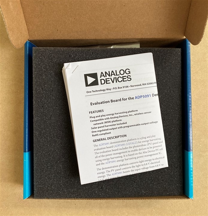
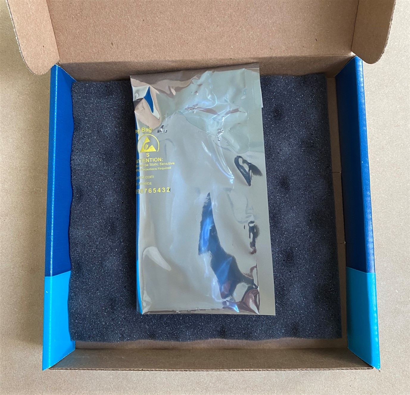
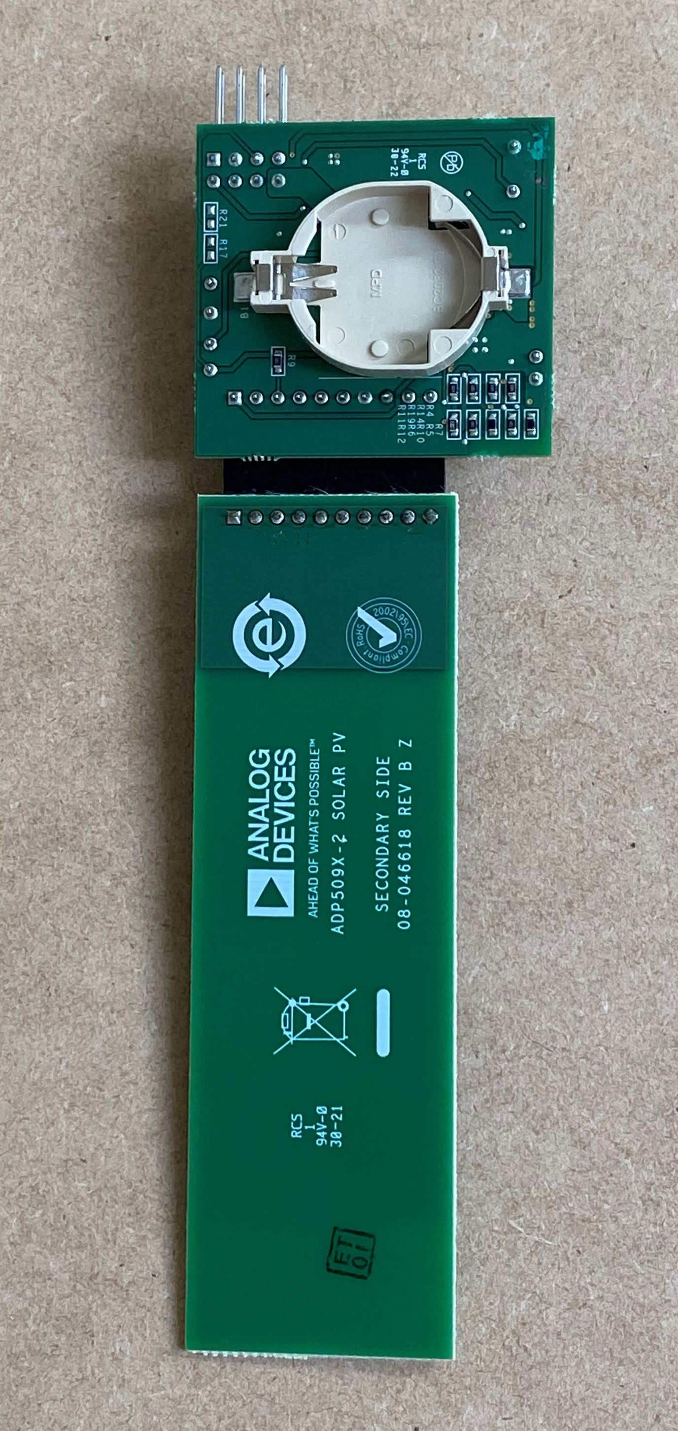
The evaluation kit came nicely packaged in a sturdy cardboard box with foam padding. A nice to have inclusion was a color printed copy of the user guide. The evaluation board and the solar PV board came pre-assembled in an anti-static bag. There is a socket for a CR2032 lithium battery that can be used to backup the super capacitor storage, but none was provided in the kit.
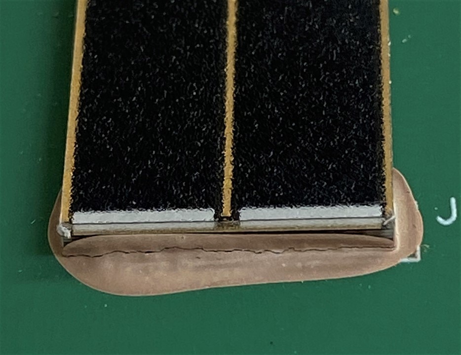
Unfortunately, there was an issue with the Alta PV board that I discovered when I initially started testing. I was getting very intermittent voltage values from the PV cells that were inconsistent with the variation in light conditions. The Alta PV cells appear to be mounted to the PCB using conductive epoxy and under close examination I noticed that one end of the attachment was fractured along the epoxy joint. Fortunately, Randall was able to get a replacement sent to me within a week, so there was minimal impact to the review timeframe. I wasn't able to get a specification for the PV board or the Alta cells, so I'm not sure why conductive epoxy was used rather than solder.
|
{gallery}Unboxing |
|---|
|
Product Box |
|
Product User Guide |
|
Anti-static packaging |
|
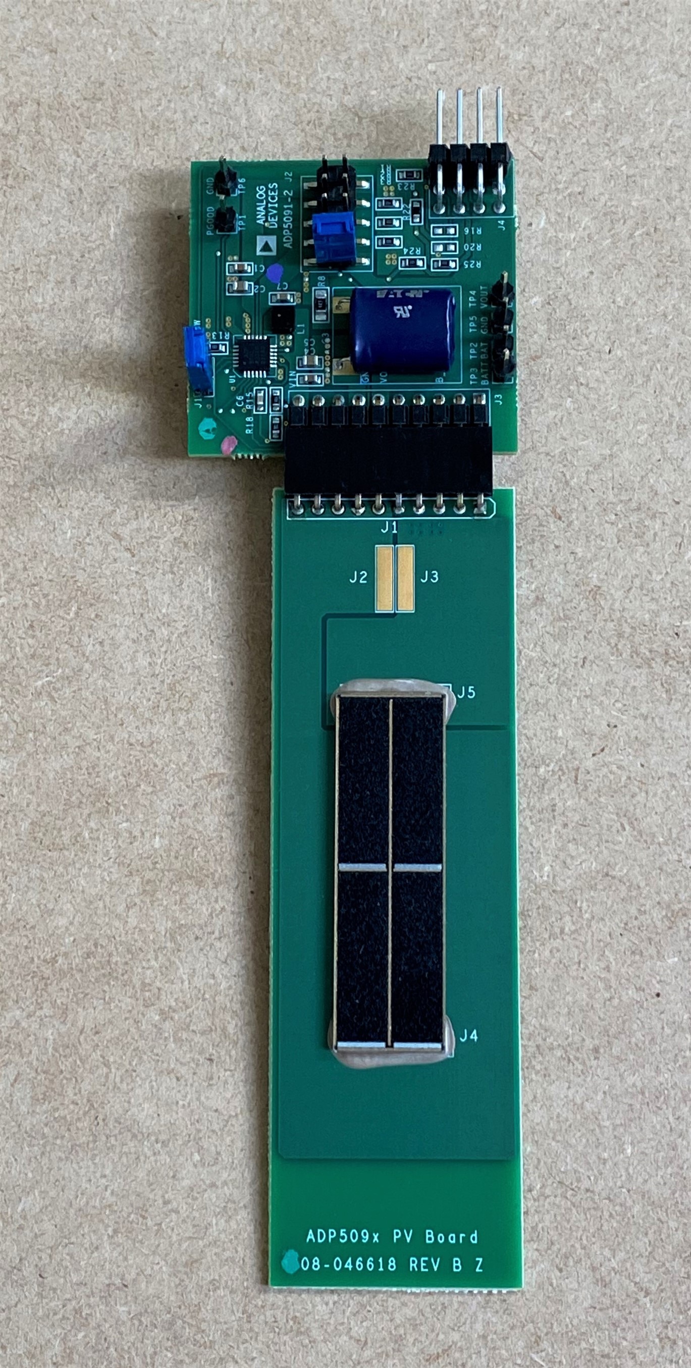
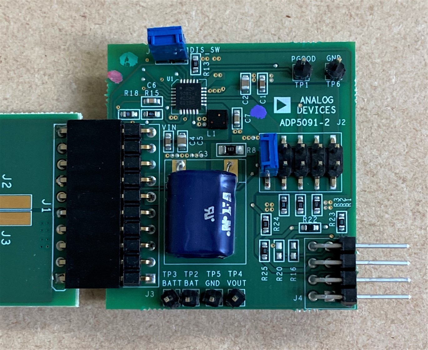
Top of Eval Board Set |
|
Bottom of Eval Board Set |
|
Closeup of Harvesting board |
Cracked conductive epoxy connection
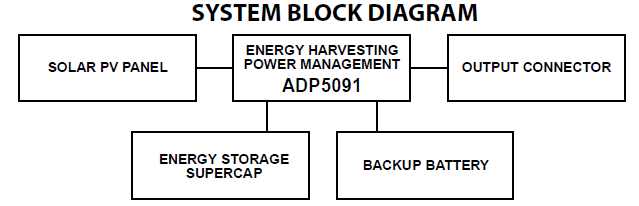
The block diagram below shows the configuration of the evaluation board set. The Alta PV cells are on one PCB and the energy harvesting circuitry is on the other. This makes it convenient to use alternate energy sources (different PV cells, piezo, or thermoelectric generators) with the harvester.
ADP5091
Efficient conversion of harvested power from 6 uW to 600mW range with submicrowatt operational losses
Ultralow power, synchronous, boost dc-to-dc regulator
Input voltage 0.38 V to 3.3 V (0.08 V to 3.3 V after cold start)
MPPT control to minimize input voltage ripple for stable dc-to-dc boost conversion
Regulated 150 mA output with resistor programmable output voltage (1.5 V to 3.6V)
Combined low droput (LDO) regulator and boost regulator
Charging control for rechargeable energy storage (supercap, rechargeable battery)
Power path management to switch output power source between energy harvester, rechargeable storage and backup battery
Alta PV Cell
Dye sensitized GaAs PV cell
Optimized for indoor environment with typical 200 lux to 1000 lux levels
Eval board
0.1 F supercapacitor for energy storage
Regulated output with jumper programmable output voltage (2.5 V, 2.8 V, 3.0 V, 3.3V)
External resistor dividers with preconfigured operating thresholds for plug and play operation with low voltage PV cells
CR2032 Backup Battery holder
Evaluation Board Schematic
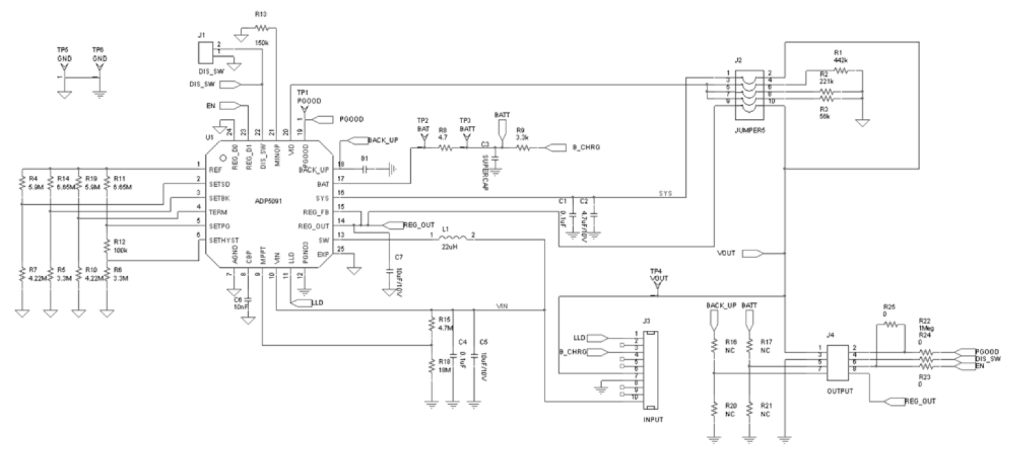
The ADP5091/ADP5092 are intelligent, integrated energy harvesting, ultralow power management unit (PMU) solutions that convert dc power from PV cells or TEGs. These devices charge storage elements such as rechargeable Li-Ion batteries, thin film batteries, super capacitors, or conventional capacitors, and power up small electronic devices and battery free systems. The evaluation board provided for this roadtest is fitted with a ADP5091ACPZ-1-R7. The only difference between the ADP5091 and ADP5092 that I could determine from the specification is that pin 11 is used for a Low Light Density (LLD) indicator on the ADP5091 and it is used for a Regulated Output Power Good (REG_GOOD) signal on the ADP5092.
The terminology used on the pins is slightly confusing. The BAT pin is where the storage element is attached (super cap, cap or storage battery). The BACK_UP pin is where CR2032 battery is attached. Applications use either the SYS pin or REG_OUT (LDO) pin to power external loads.

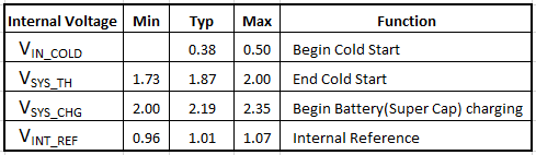
As you can see from the detailed block diagram the PMU operation is controlled by a set of threshold voltages. A few are fixed within the part and the others are externally set using high resistance resistor dividers.
These are the fixed voltages.
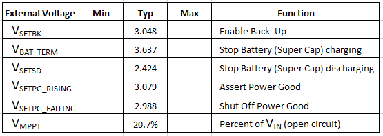
These are the configurable voltages calculated using the resistor values used on the Eval board (formulas are in the ADP5091/5092 specification).
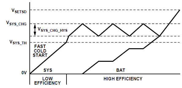
Initially, when VIN < VIN_COLD, the harvester circuit is off (low light, VSYS < VSYS_TH). When VIN > VIN_COLD (0.38 V), the capacitor on the SYS pin begins charging (cold start). When VSYS > VSYS_TH (1.87 V), the main boost regulator and charge controller start working. When VSYS > VSYS_CHG (2.19 V), the storage element on the BAT pin starts charging. If VSYS < VSYS_CHG (with hysteresis), the storage element stops charging and VIN returns to charging the VSYS capacitor to ensure it does not enter cold startup. If VSYS < 0.08 V, it returns to cold startup.
The sequence is illustrated in the figure below:
The switching mode boost regulator operates in synchronous and asynchronous modes. The boost regulator operates in the synchronous mode when VBAT_TERM > VSYS > VSETSD (when the storage element is charging). The boost regulator shuts downs when VSYS > VBAT_TERM (to stop charging the storage element) or when the CBP pin voltage < MINOP voltage [~ 300 mV on the eval bd] (to stop the boost circuit when there is insufficient input energy). Otherwise, the boost regulator runs in asynchronous mode.
A DIS_SW pin is available for the sensor/MCU to disable the boost regulator termporarily to prevent switching noise from interfering with RF operation.
As mentioned earlier, the harvester can power an external circuit from either the SYS or REG_OUT pins. The SYS pin will have a large range when the boost is operating (2 V - 3.6 V), so I'm going to use the LDO output on the REG_OUT pin for my sensor circuit. The LDO output voltage is programmed by a voltage divider on the VID pin over a range of 1.5 V to 3.6 V. On the Eval board it is jumper selectable for 2.5, 2.8, 3.0, or 3.3 V. I'll be using 3.3 V for a Xiao nRF52840 and sensor. The LDO has a output current of 150 mA with a current limit of 260 mA. LDO dropout is 200 mV below the programmed output.
For more detailed operational description, I've attached copies of the PDF specification files to the review.
In order to evaluate the Energy Harvester operation, I created the test setup shown below using a 3D printed baseplate:
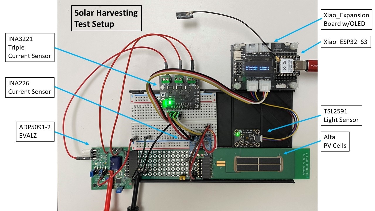
The setup uses a Xiao ESP32S3 MCU to monitor and upload the following sensor information:
All sensors are interfaced via I2C. The Xiao uploads MQTT data via WiFi to a Node-Red Dashboard and an Influx database. The Xiao also displays debug info on an OLED display. The Xiao and sensors are powered separately from the Harvester circuit using USB or a USB power bank.
The TSL2591 is not calibrated and I don't have a calibrated reference or source, but I'm hoping that the Lux computations from the visible and IR sensors are reasonably close and it will give me a relative measure of the available light plus allow me some degree of repeatability for my test data.
I also tested the harvester using monocrystalline Silicon PV cells as shown below:
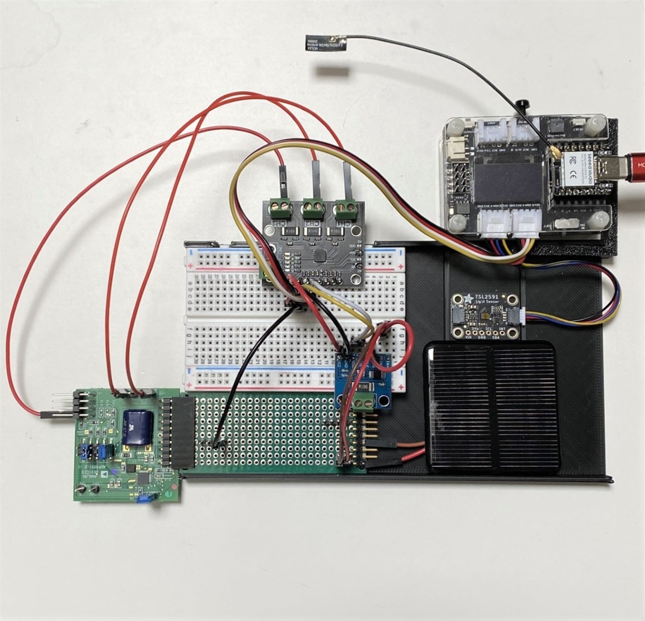
I am using two different types of PV cells to test the harvester, the Alta GaAs cells provided with the evaluation kit and generic monocrystalline Silicon cells that I purchased from Amazon (I've used these in outdoor project). Unfortunately, I don't have detailed specifications for either of the cell types. The Silicon cell assembly output is described as 2V @ 160mA. I have no specific information on the Alta GaAs cells - there was no information provided with the kit.
From general information that I obtained from searches for single junction cells, the GaAs cells should be more efficient that the monocrystalline Silicon cells - (21% vs 29%). GaAs cells also have lower leakage current and lower temperature coefficients, so should perform better in lower illumination and higher temperture envionments.
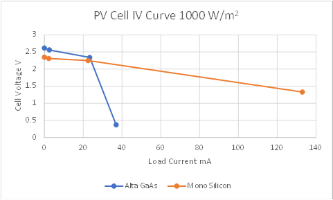
The Silicon cell assemblies have larger surface area than the GaAs cell assemblies (1849 mm^2 vs 480 mm^2), so I would expect higher power available. I don't have calibrated light sources, but Silicon panels are generally spec'ed at an irradiance of 1000 W/m^2, temperature of 25C and perpendicular incidence angle. I do have a calibrated irradiance meter, so I measured the two cell panels on a sunny day when I could get spec conditions. Unfortunately, I don't have an SMU to generate a continuous load curve, so I just tested with fixed resistors (OC, 1K, 100, 10) to obtain the following plot. The GaAs panel had a higher open circuit voltage, but a lot less available current (short circuit current looks like it might scale with the cell area).
I'll be using these cells indoors for testing the harvester, so there will be substantially less energy and the available light spectrum will be different. Bright LED lights in an office might be able to achieve illumination values of 1000 Lux which is roughly equivalent to about 8 W/m^2. From a 2017 conference presentation that I found I would expect to be able to harvest about 130 uW @ 200 Lux from a 10 cm^2 GaAs solar cell, so it appears that it will be extremely challenging to sustain an IoT sensor without a lot of power optimization.
For my initial tests to verify that my setup was working, I started with the Silicon PV module as the harvester input as it has a larger available current.
This test was done using illumination from a skylight above my desk on a cloudy day. Indoor temperature was 24 C. I started with the SuperCap discharged.
Here is the data displayed on my Node-Red Dashboard.
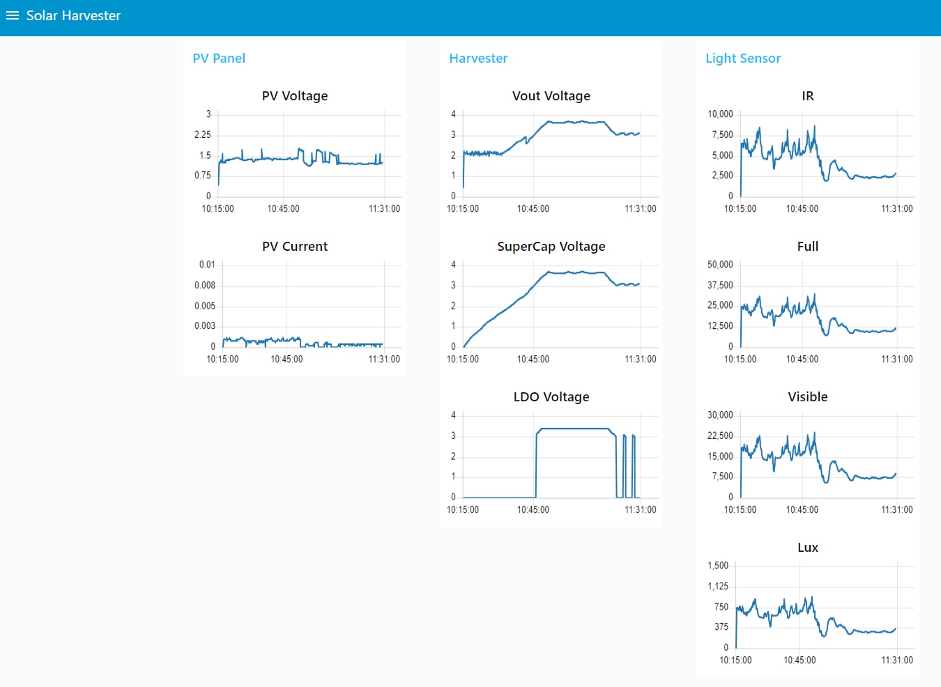
This is the same data extracted from InfluxDB and plotted in Excel. When I started the test the illuminance was about 700 Lux which resulted a PV output of 1.4 V @ 1 mA and it later dropped to 300 Lux with a PV output of 1.2 V @ 0.4 mA. The overlay shows the phases of the harvester operation.
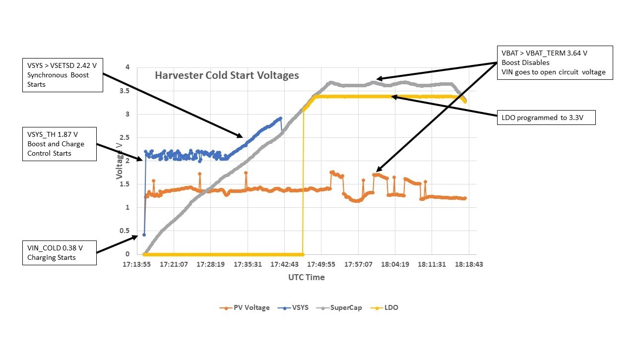

Toward the end of the test, I applied a 10 K resistor to the LDO output (330 uA load). This was in the lower illuminance phase (300 Lux), so that the PV input was not able to sustain the load and the SuperCap started to discharge. When the LDO output reached 3 V it switched off (disconnected the load). The SuperCap was then able to charge to allow the LDO to turn on temporarily, but the load would cause it to turn off. The input power was about 0.5 mW and the load power was about 1 mW. At 700 Lux the input power was about 1.4 mW, so that would have sustained the load.

I tried the same experiment with the Alta PV module, but it was only able to get to 0.41 V @ 700 Lux and could not generate enough current start the charging. I decided to use a ring LED lamp that would me to adjust the illuminance up to about 1300 Lux.
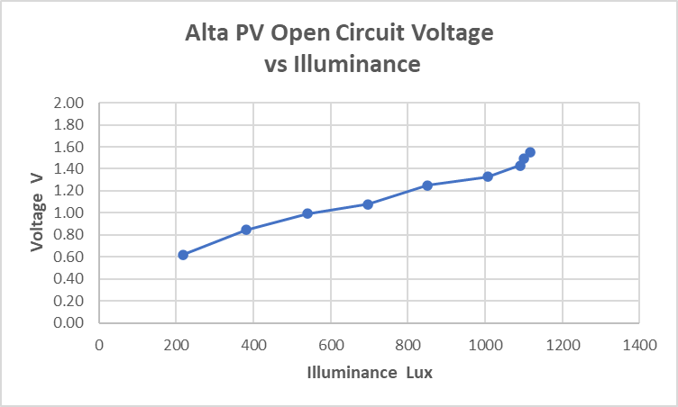
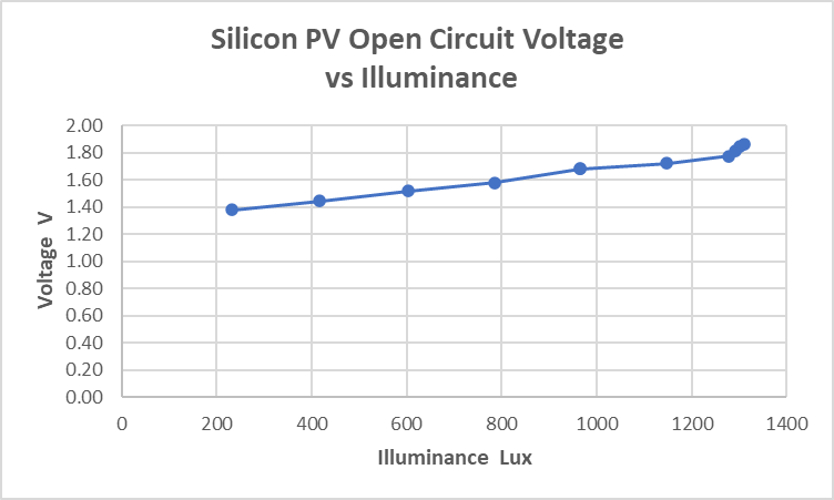
PV Open Circuit Voltage vs Illuminance
Using a ring LED light in close proximity to the PV cells (> 6 inches), I was able to get illuminance values of ~ 1100 - 1300 Lux. The LED light allows me to step the light intensity in discrete steps to characterize the PV voltage without the harvester load (open circuit) and PV voltage and current with the harvester attached. There was some variation in the available illuminance as I swapped between the Alta and SIlicon PV setups, so the max illuminance was 1100 Lux in the Alta seup vs 1300 Lux in the Silicon setup, but I wouldn't have anywhere close to that amount in a normal configuration so I don't think it affects the overall assessment.
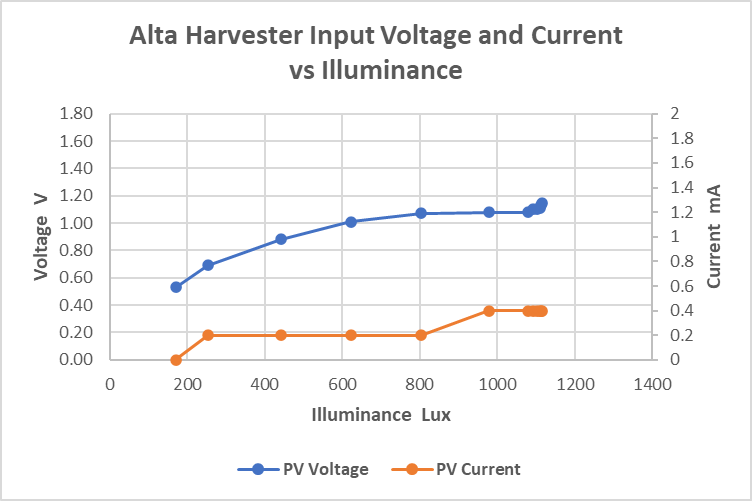
PV Voltage and Current with harvester attached
These measurements are made in the initial SuperCap charging mode.
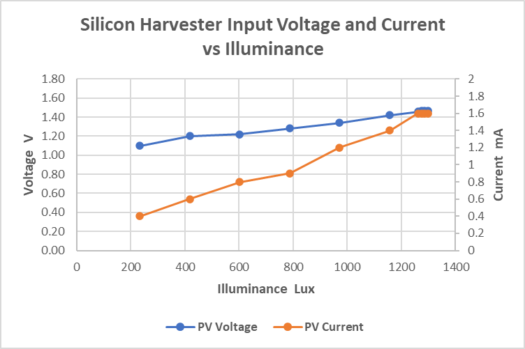
The Silicon cells have a clear advantage, much of it due to the larger cell area. I measured the normal illuminance that I get at my desk using overhead LED lights and it was only 150 Lux. I have read that normal illuminance for a business office is 500 - 1000 Lux, so I guess my low value is due to having fewer lights in my home office (I only have two 850 lumen, 2700K lights overhead since during the day I get natural light through the skylight). Anyway it is clear from the data that the Alta PV board may not work well in my environment.
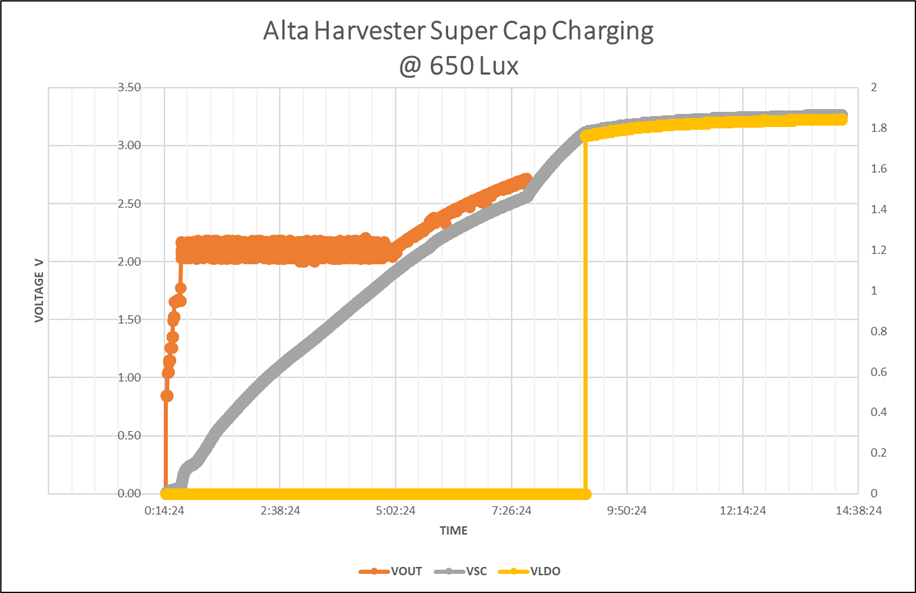
SuperCap Charge time check
As sort of a sanity check, I picked a point where the harvester was operating and timed how long it would take the Alta PV cells to charge the SuperCap from 0 to 3.1V (where the LDO would start). At 650 Lux, the Pv was at 1V with 200uA of current. It took 8 3/4 hours to charge the 0.1 F capacitor.
Efficiency check
I switched to the Silicon setup to check the efficiency as it should improve with increasing input voltage. Here is a plot from the AD5091 spec. I should be on the red curve (SYS = 2 V).
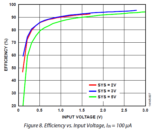
I am using the LDO, so that will affect the efficiency. I put a 10 K resistor on the LDO output (3.3 V), so there is a nominal 330 uA load for about 1 mW. I adjusted the illuminance until I reached the point where the Harvester would no longer charge the SuperCap, but would maintain the LDO output (so power in vs power out was balanced). I realized the right way to do this is with an SMU in place of the PV input, but unfotrunately I don't have one and I hadn't planned on it for the roadtest.
The equilibrium point occurred at 1010 Lux with PV voltage of 1.4 V and current of 1.2 mA.
Input power = 1.4 V x 1.2 mA = 1.68 mW
Output power + 3.3 V x 330 uA = 1.09 mW
Efficiency = 1.09 / 1.68 = 65 %
The LDO efficiency is not spec'ed, but if we assumed that it was 80 % and the harvester efficiency is 80 - 90 %, then the overall efficiency should be in the range of 64 - 72 %. So, while my calculation seems a bit low - it might be okay. Another problem that I realized with my test setup is that the resolution of the current sensor that I am using on the PV input is 200 uA which will add to possible inaccuracies in my data.
As part of the roadtest, I had intended to see if I could power a simple BLE beacon using the harvester in my normal indoor working environment. A beacon is a simple way to make sensor data available to a smartphone or other device in the proximity of the sensor. Beacons are not ultra low power since they need to continuously advertise their presence when they are not connected. From prior experience trying beacon examples, I had come up with a target of needing an average of about 1 mW continuously to operate. That's the reason I've been testing with a 10 Kohm resistive load on the LDO. With that load and indoor lighting I determined that the Alta cells would not work and the Silicon cells would need about 1000 Lux of illuminance to work without adding the backup CR2032 cell to the harvester. I decided that I should implement a beacon and see if I could reduce its power requirement to a value that would be supported by the SuperCap and an illuminance value of 150 Lux.
I am going to use a Seeed Xiao BLE which uses an nRF52840 MCU. I will use a Nordic PPK2 Power Profiler to characterize the beacon power requirement. I will power the Xiao from 3.3 V to emulate the LDO output. I am not going to add a sensor for this experiment as the beacon power will be dominated by the BLE radio operation.
The setup is shown below. I am using the beacon Arduino example code from the Adafruit Bluefruit library

beacon.ino
/*********************************************************************
 This is an example for our nRF52 based Bluefruit LE modules

 Pick one up today in the adafruit shop!

 Adafruit invests time and resources providing this open source code,
 please support Adafruit and open-source hardware by purchasing
 products from Adafruit!

 MIT license, check LICENSE for more information
 All text above, and the splash screen below must be included in
 any redistribution
*********************************************************************/
#include <bluefruit.h>

// Beacon uses the Manufacturer Specific Data field in the advertising
// packet, which means you must provide a valid Manufacturer ID. Update
// the field below to an appropriate value. For a list of valid IDs see:
// https://www.bluetooth.com/specifications/assigned-numbers/company-identifiers
// 0x004C is Apple
// 0x0822 is Adafruit
// 0x0059 is Nordic
#define MANUFACTURER_ID   0x0059

// "nRF Connect" app can be used to detect beacon
uint8_t beaconUuid[16] =
{
  0x01, 0x12, 0x23, 0x34, 0x45, 0x56, 0x67, 0x78,
  0x89, 0x9a, 0xab, 0xbc, 0xcd, 0xde, 0xef, 0xf0
};

// A valid Beacon packet consists of the following information:
// UUID, Major, Minor, RSSI @ 1M
BLEBeacon beacon(beaconUuid, 0x0102, 0x0304, -54);

void setup()
{
  Serial.begin(115200);

  // Uncomment to blocking wait for Serial connection
  // while ( !Serial ) delay(10);

  Serial.println("Bluefruit52 Beacon Example");
  Serial.println("--------------------------\n");

  Bluefruit.begin();

  // off Blue LED for lowest power consumption
  Bluefruit.autoConnLed(false);
  Bluefruit.setTxPower(0);    // Check bluefruit.h for supported values

  // Manufacturer ID is required for Manufacturer Specific Data
  beacon.setManufacturer(MANUFACTURER_ID);

  // Setup the advertising packet
  startAdv();

  Serial.println("Broadcasting beacon, open your beacon app to test");

  // Suspend Loop() to save power, since we didn't have any code there
  suspendLoop();
}

void startAdv(void)
{
  // Advertising packet
  // Set the beacon payload using the BLEBeacon class populated
  // earlier in this example
  Bluefruit.Advertising.setBeacon(beacon);

  // Secondary Scan Response packet (optional)
  // Since there is no room for 'Name' in Advertising packet
  Bluefruit.ScanResponse.addName();

  /* Start Advertising
   * - Enable auto advertising if disconnected
   * - Timeout for fast mode is 30 seconds
   * - Start(timeout) with timeout = 0 will advertise forever (until connected)
   *
   * Apple Beacon specs
   * - Type: Non connectable, undirected
   * - Fixed interval: 100 ms -> fast = slow = 100 ms
   */
  //Bluefruit.Advertising.setType(BLE_GAP_ADV_TYPE_ADV_NONCONN_IND);
  Bluefruit.Advertising.restartOnDisconnect(true);
  Bluefruit.Advertising.setInterval(160, 160);    // in unit of 0.625 ms
  Bluefruit.Advertising.setFastTimeout(30);      // number of seconds in fast mode
  Bluefruit.Advertising.start(0);                // 0 = Don't stop advertising after n seconds
}

void loop()
{
  // loop is already suspended, CPU will not run loop() at all
}
Here is the beacon connected with the nRF Connect app on my iPad.

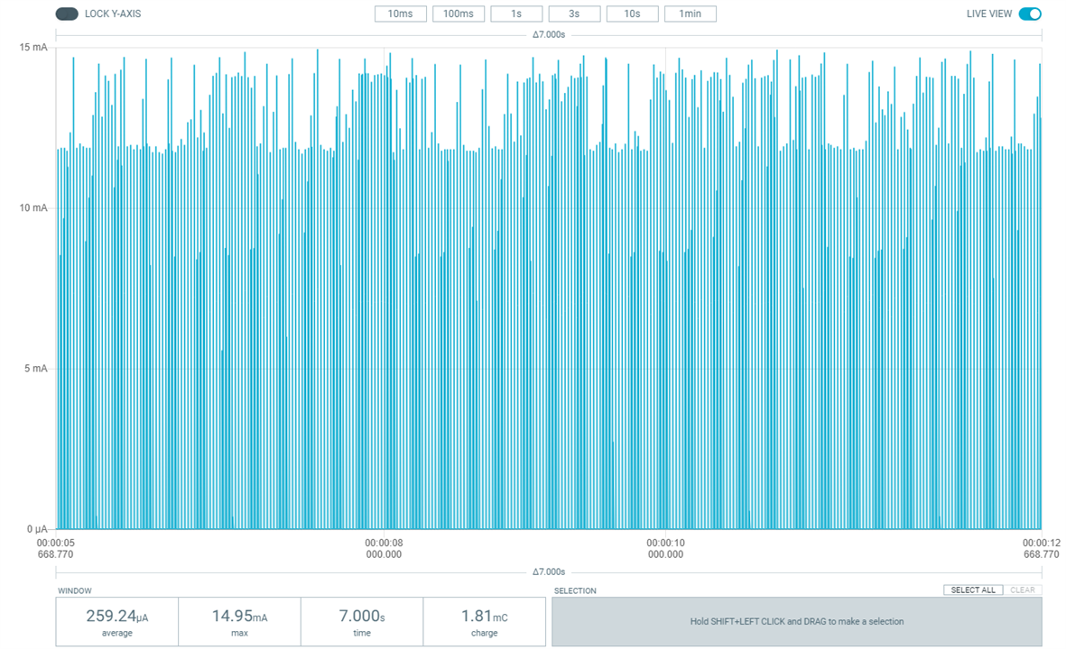
The beacon advertising power at the default settings with 100 ms intervals averages about 255 uA (0.84 mW). The BLE radio is using about 15 mA peak current.
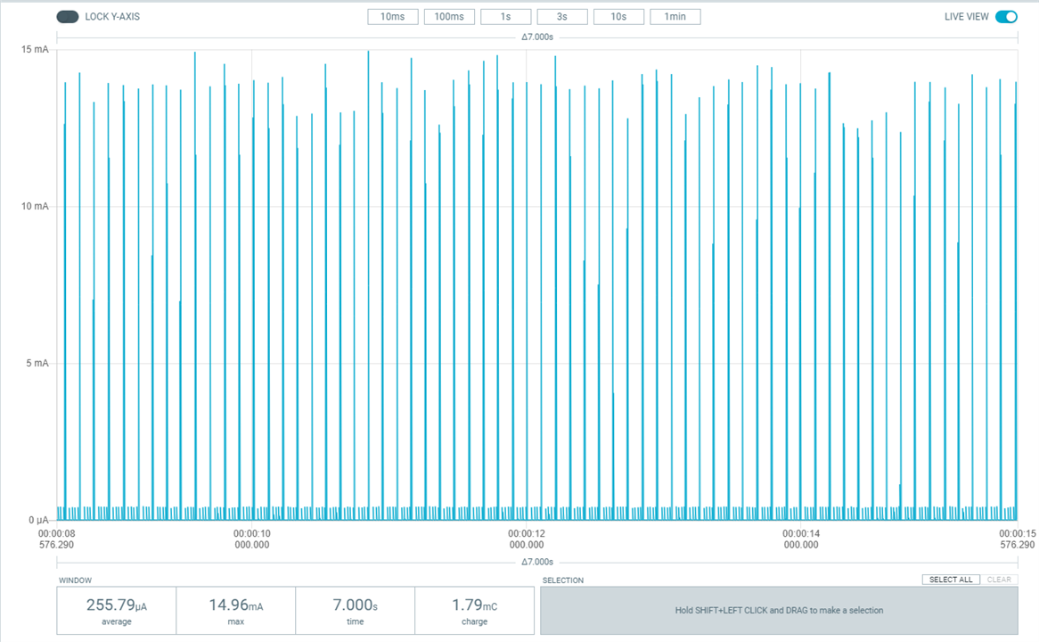
The default power while connected to the app. Using a custom app I could manage the connection time to just what was required to receive the sensor data and also manage the connect intervals, so the average overall power would not be much above the advertising power. I don't have the time to do that unfortunately.
So, how can we reduce advertising power? I have read that to reliably detect a beacon that Apple devices require a minimum once per second advertising rate, so the interval could be increased to 1 second.
In the Bluefruit library you can set a fast and slow advertising interval. I don't think that I need the fast advertising rate, so I'll set them both to 1 second.
Default code (100 ms):
Bluefruit.Advertising.setInterval(160, 160); // in unit of 0.625 ms
Updated code ( 1 s):
Bluefruit.Advertising.setInterval(1600, 1600); // in unit of 0.625 ms
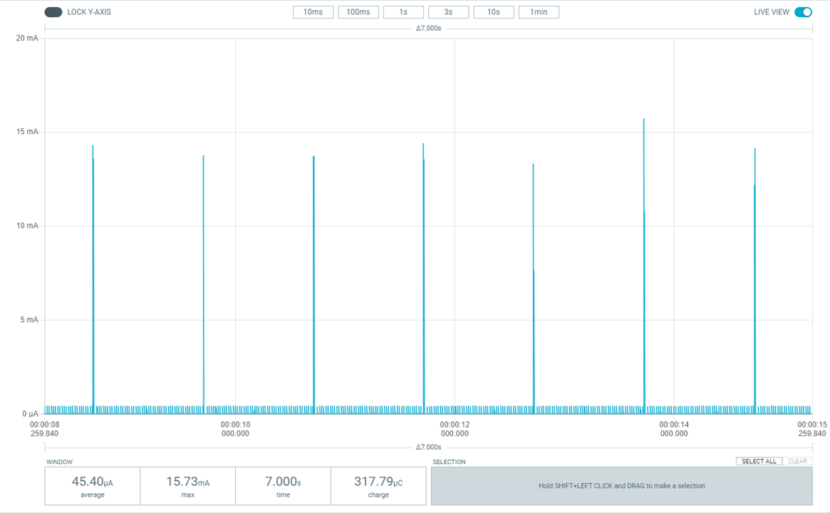
Here is the updated average advertising power (about 45 uA, 0.15 mW):
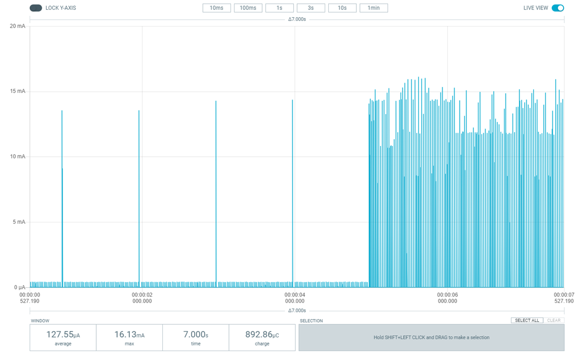
And an updated composite average (advertising 60 %, connect 40 %):
Power vs Illuminance curve generated from my previous data:
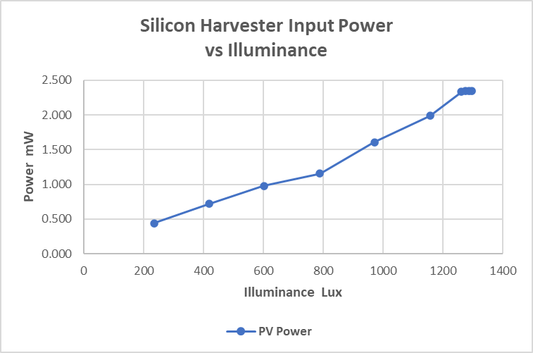
Making an assumption that I could keep the average beacon power to 0.20 mW with the overall harvester efficiency at 65 %, I would need 0.30 mW of power from PV input. Extrapolating the power curve would give me 0.32 mW at 150 Lux, so it would be possible to power a beacon with the caveat that the light would have to be on continuously or the beacon would need to power down if the light were off. A project for the future.
As always the roadtest was a learning experience. Thanks to E14, Randall, and Analog Devices for the opportunity to try out the Energy Harvesting kit.
The ADP5091 is an interesting device with configurability to work with different low energy sources. If I could change one thing, it would be to add internal configuration and monitoring capability via I2C like many of the newer PMIC devices. That being said, it is still a very capable and useful device.
I didn't achieve all that I had wanted with the roadtest, partly due to issues with the kit and partly due to issues with my setup.
Kit Issues
Setup Issues
My biggest disappointment with the roadtest was the failure to be able to demonstrate the very low power energy harvesting capability (down to 6 uW) that the device is spec'ed to achieve. A precision SMU would have helped a lot, but maybe was out of scope for this roadtest. The other disappointment was the poor performance of the Alta GaAs PV cells.
Product Performed to Expectations - I did have a defect with the first PV board that I received, but that was quickly replaced. I had hoped to get better indoor performance out of the Alta PV cells. I've never used GaAs cells before, but they are supposed to have efficiencies around 30 % and the Eval User Guide describes them as "optimized for indoor environments, where lux levels are typically 200 lux to 1000 lux". Unfortunately, there was no spec on the PV board and I could not achieve that level of performance in my testing. The harvester itself was functionally as I expected, but I would have preferred if the default configuration had hybrid mode enabled on the regulator.
Specificatiion were sufficient to design with - there were a couple minor label issues with plots in the ADP5091/5092 specification.
Demo Software was of good quality - wasn't sure what to do here as there was no demo software, should have been an N/A. I just gave it 3 stars. It would have been nice if the software that they use with their WSN demo boards was available - could not even find documentation on those boards although they do show images of them in their literature. They even show a WSN demo board connected to the harvester.
Product was easy to use - one thing that prevented me from doing a better review is that changing many of the device configurations on the eval board required removing or replacing SMD resistors. That's currently beyond my skillset, so I was not able to evaluate some of the device capabilities.
Support materials were available - I was not able to get the specification of the Alta PV board, although Randall did try his Analog Devices contact.
The price to performance ratio was good - the eval board set cost $58 which is reasonable. The bare part is only $8.