RoadTest: Review the Arduino Opta Micro-PLC
Author: MARK2011
Creation date:
Evaluation Type: Evaluation Boards
Did you receive all parts the manufacturer stated would be included in the package?: True
What other parts do you consider comparable to this product?: VersaMax Micro; TSX Micro Schneider; Siemens LOGO; Moeller/Eaton EASY; SBC PLCs
What were the biggest problems encountered?: Some doubts running Arduino PLC IDE. I was unable to program Arduino Opta in that environment. I had constant hang-ups/ freezing. An essential procedure of Memory-partitioning wasn't clearly communicated (or I didn't read instructions carefully)
Detailed Review:
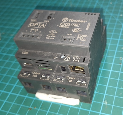
I just wanted to take a moment to say a huge thank Arduino, Finder and element14 Team for inviting me to participate in the Roadtest project and for providing the Arduino Opta Micro-PLC.
It’s been an exciting and insightful experience, and I really appreciate giving me that chance to dive into such a great product.
The Opta has proven to be a fantastic tool, and I’ve enjoyed testing its features and capabilities.
I’m looking forward to sharing my findings and seeing how this technology will continue to shape the future of automation.
Thanks again for this wonderful opportunity — it’s been a pleasure to deal with this interesting device.
And by the way, I guess choosing the Arduino Opta for this RoadTest was the OPTA-mal decision!
The Arduino Opta Micro-Programmable Logic Controller (PLC), developed in collaboration with Finder, represents a cutting-edge solution for industrial automation and the Industrial Internet of Things (IIoT), offering robust hardware, support for IEC 61131-3 programming, and IoT connectivity options. Combining the reliability and flexibility of the Arduino platform with industrial-grade performance and security, the Opta PLC is designed to meet the needs of modern automation systems. It offers a range of capabilities for real-time control, connectivity, and secure cloud integration, making it an ideal choice for applications across various industries, from manufacturing and process control to predictive maintenance. Testing the Opta allowed me to evaluate its key features, such as input/output functionality, connectivity, and compatibility with industrial communication protocols like Modbus. This was possible because I received the Opta variant with Modbus for testing.
If I have to start, it's best to begin at the beginning. And the beginning lies in the story of two companies.
Finder is an Italian company founded in 1954, specializing in the design and manufacturing of high-quality industrial automation components, including relays, timers, and PLCs. Known for its innovative products, Finder has been at the forefront of providing solutions for control systems, with a focus on reliability and ease of use. The company's PLCs, are designed for industrial automation and IoT applications, combining advanced features with user-friendly programming environments.
Arduino is an open-source electronics platform founded in 2005, designed to make it easy for people to create interactive projects. It consists of hardware (microcontroller boards) and software (Arduino IDE), enabling users to program devices to interact with sensors, lights, motors, and other electronics. Arduino’s simplicity, accessibility, and community-driven development have made it a popular choice for hobbyists, educators, and professionals in fields such as automation, robotics, and IoT.
This report documents the testing of the Arduino Opta Micro-PLC, focusing on its core features, performance, and functionality. The primary objective of the testing was to evaluate its programming capabilities, I/O performance, real-time control, security features, and communication protocols, including Modbus RTU and Modbus TCP. Additionally, the integration of IoT connectivity, secure OTA firmware updates, and the device’s compliance with industrial standards were tested to ensure the Opta’s suitability for industrial environments.
The results of this testing confirmed the performance, reliability, and potential use cases of the Arduino Opta Micro-PLC in various automation and IoT-driven applications. The report outlines the testing process and results for the Arduino Opta Micro-PLC, specifically the model equipped with Modbus protocol support. The aim was to evaluate its performance, connectivity, and compatibility within automation tasks requiring Modbus communication, using the RS-485 interface. The findings provide insights into the capabilities and reliability of the Opta Micro-PLC in Modbus-enabled environments.
The Modbus is a serial communication standard and has become a de facto standard communication protocol and is now a commonly available means of connecting industrial electronic devices. In Modbus RTU and Modbus ASCII RS485 is used as the physical layer. It is possible to use an Opta as Slave (and with some restrictions also as Master) in Modbus applications, but a RS485 interface is needed.
Modbus protocol support is a key feature that enables reliable and standardized communication in industrial automation. Modbus offers benefits such as easy integration, interoperability with various devices, and robust data exchange over RS-485, making it ideal for real-time monitoring and control. My testing focused on assessing the performance and connectivity of the Opta Micro-PLC within Modbus-based systems.

The Arduino Pro Family is a collection of industrial-grade development boards and embedded solutions designed to bring the power of Arduino's open-source ecosystem to the world of industrial automation and the Industrial Internet of Things (IIoT). These products are aimed at professionals in sectors such as manufacturing, automation, energy, and smart cities, offering a combination of reliability, performance, and flexibility.
Arduino has traditionally been known for its accessible, hobbyist-friendly platforms, but the Arduino Pro Family is specifically engineered for more advanced and professional applications, with a focus on industrial use cases. The key to its success is its ability to bring easy-to-use development tools alongside rugged, reliable hardware designed for industrial environments.
The Arduino Pro family includes boards and modules for a variety of industrial applications:
With products like the Arduino Opta, Portenta, MKR, and Industrial Shields, the Arduino Pro Family provides powerful processing, real-time control, data collection, and IoT communication capabilities that can be deployed in factory automation, remote monitoring, predictive maintenance, and much more.
The Arduino Opta is one of the flagship products in the Arduino Pro Family and a true industrial-grade programmable logic controller . It is developed for real-time control in industrial environments and integrates with both traditional and IoT-based systems. The Opta is designed with robust industrial communication standards like Modbus RTU (RS-485) and Modbus TCP (Ethernet), and it is particularly suited for applications like smart buildings, process control, and automated production lines.
The Portenta series is designed for applications that require higher processing power and advanced capabilities such as machine learning and edge computing. The Portenta H7 features a dual-core Arm Cortex-M7 and M4 processor, providing the processing power necessary for AI and real-time control tasks as Machine Learning at the Edge; supports various communication protocols such as Ethernet, Wi-Fi, Bluetooth, and LoRa.
The MKR series is a family of smaller, low-power boards designed for IoT applications. While these devices are not as rugged or powerful as the Opta or Portenta series, they offer great flexibility for remote monitoring, control, and sensor networks in industrial environments. The MKR boards are optimized for low-power operation, which makes them ideal for battery-powered sensors or long-term monitoring applications. Support Wi-Fi, LoRa, NB-IoT, and GSM.
The Arduino Pro line is designed for more demanding industrial and commercial applications, and the Arduino Opta Micro-PLC fits this profile perfectly. While traditional Arduino boards such as the Uno or Mega are great for prototyping and simple applications, the Opta Micro-PLC offers much higher performance, which is essential for complex industrial tasks.The lower-end Arduino models rely on simpler microcontrollers like the ATmega328P, which offer lower clock speeds and less processing power, making them unsuitable for real-time industrial applications. Other Arduino Pro devices, such as the Portenta H7, may offer similar levels of processing power but lack specialized industrial communication features like RS-485 or high-power relay outputs, which make the Opta specifically suited for PLC applications.
The collaboration between Arduino and Finder represents a strategic partnership that combines Arduino's open-source platform and Finder's expertise in industrial automation and switching technology. This partnership aims to deliver powerful, secure, and reliable industrial solutions for automation systems, smart factories, and IIoT applications.
Finder is renowned for its high-quality industrial relays and switching technology, with decades of experience in providing reliable solutions for industries like automotive, energy, telecommunications, and process control.
The Arduino Opta Micro-PLC is a perfect example of how the Arduino-Finder partnership enhances the capabilities of industrial automation systems. By integrating Finder’s industrial-grade components with Arduino’s flexible and programmable platform, the Opta provides both ease of use for developers and reliability for industrial systems.
The film below captures the exciting unboxing experience of the Arduino Opta Micro-PLC! The device arrived securely and neatly packed, and its sleek, professional design immediately impresses. Every detail, from its aesthetic build to the robust packaging, highlights its quality and readiness for applications. A promising first look at a powerful tool for automation!
Video: 01.unboxing.OPTA.
The unboxing process assessing summary:
Packaging: Condition of the OPTA and packaging integrity was perfect.
Inclusions: In the box I found OPTA device, shorted “Getting started” manual (leaflet), no additional accessories
Visual inspection: All looked great, no physical damage or defects.
Although the box only contains a simplified manual, Arduino Opta Micro-PLC is supported by extensive documentation, easily accessible on the product page
The Arduino Opta is designed for industrial automation and IIoT (Industrial Internet of Things) applications, and as such, it comes with a comprehensive set of user manuals, technical documentation, and installation guides to ensure smooth setup, configuration, and operation. These documents provide crucial information for both engineers and developers to get the most out of the device.
Here is a breakdown of the key user manuals, documentation, and installation guides that support the Arduino Opta Micro-PLC
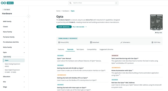
https://docs.arduino.cc/hardware/opta/#tutorial
The user manual for the Arduino Opta Micro-PLC provides a comprehensive overview of the device covering its major hardware and software elements, its capabilities, and step-by-step instructions on how to use it for applications. This manual is targeted toward users who are setting up and operating the device in their systems.
https://docs.arduino.cc/tutorials/opta/user-manual/
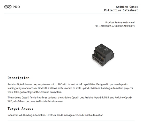
The technical documentation provides a more in-depth exploration of the Opta Micro-PLC's features, capabilities, and specifications, including detailed descriptions of the hardware architecture, communication protocols, and software features. This documentation is mainly aimed at engineers, system integrators, and developers who need to integrate the Opta Micro-PLC into industrial automation systems.
The installation guide for the Arduino Opta Micro-PLC provides step-by-step instructions for setting up the device in an industrial environment. It includes detailed instructions on physical installation, wiring, and network configuration.

In addition to the user manual and technical documentation, Arduino provides a variety of sketches, libraries, and tutorials specifically designed for the Opta Micro-PLC. These resources make it easier for users to get started with the device, configure it for their specific needs, and implement automation logic using both Arduino programming and IEC 61131-3 PLC languages.
As IoT plays a central role in the Opta Micro-PLC’s capabilities, there are specific guides and documentation focused on integrating the device with cloud platforms such as Arduino Cloud and third-party IoT services.
Last not least
Opta comes with convenient leaflet containing basic information, diagrams etc
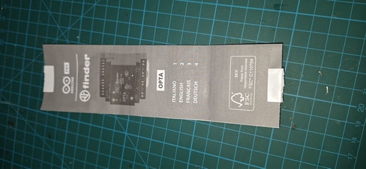
I tried to assess clarity, depth of information, and comprehensiveness in guiding users through initial setup, programming, and advanced configurations.
I also checked whether the documentation provides sufficient information on used standards, IoT integration, and Modbus RTU/TCP usage.
The Arduino Opta Micro-PLC is supported by a wide range of user manuals, technical documentation, and installation guides designed to help users set up, program, and integrate the device into industrial systems with ease. These resources cover everything from hardware setup and communication protocols to cloud integration and security features. Combined with Arduino sketches, libraries, and tutorials, these documents ensure that both beginners and advanced users can effectively utilize the Opta for automation and IIoT applications.
I spent time (much more than I expected and planned) exploring and understanding the Arduino Opta Micro-PLC hardware, features, and key specifications
A PLC (Programmable Logic Controller) is an industrial digital computer designed to control machinery and automate processes. It is highly reliable, can be programmed to perform specific tasks, and interacts with input/output devices like sensors, switches, and motors to execute complex control functions in manufacturing, automation, and other industrial environments.
The Arduino Opta Micro-PLC is an industrial-grade Programmable Logic Controller developed by Arduino in partnership with Finder. It is designed to meet the needs of automation and Industrial Internet of Things (IIoT) applications, with a focus on reliability, connectivity, and security. The Opta integrates high-performance components, extensive I/O capabilities, and robust communication interfaces to provide a flexible solution for industrial environments. Below is a detailed overview of the key hardware components of the Arduino Opta Micro-PLC
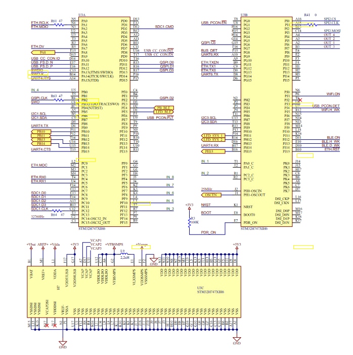
At the heart of the Arduino Opta Micro-PLC is the STM32H747XI (Dual-core Cortex-M7 + Cortex-M4) microcontroller, a powerful and efficient solution from STMicroelectronics. This microcontroller plays a critical role in the device’s performance, handling real-time control, processing, and communication tasks.
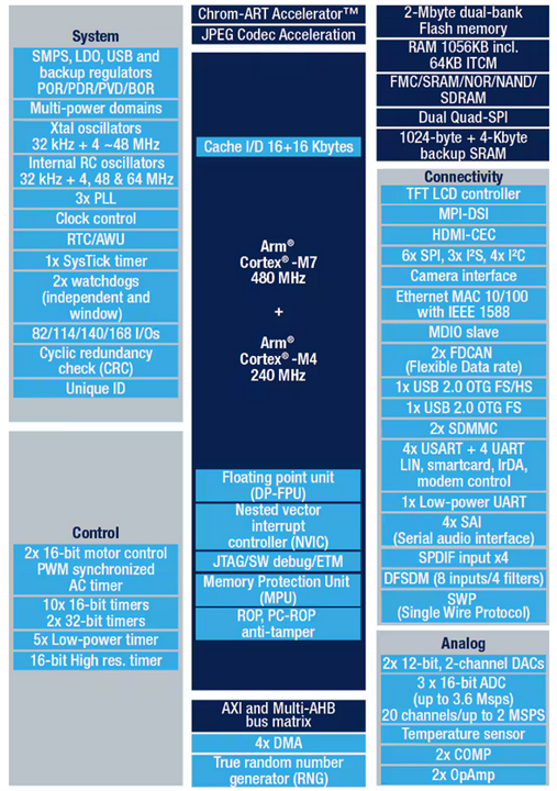
The Arduino Opta Micro-PLC is equipped with a comprehensive set of I/O modules that allow it to interact with a variety of industrial devices, sensors, and actuators. These I/O ports enable the Opta to be used in a wide range of automation tasks, from simple control processes to complex monitoring and actuation.
Communication plays a central role in the Opta Micro-PLC, as it is designed to be integrated into industrial networks and IIoT ecosystems. The Opta supports multiple communication ports for both local and cloud-based connectivity.
Security is a critical aspect of industrial IoT devices, and the Arduino Opta Micro-PLC incorporates advanced hardware-level security features to protect both the hardware and software. One of the key security features is the ATECC608B secure element from Microchip Technology. ATECC608B ensures that the device can communicate securely over the network. This is particularly important for IoT applications, as the Opta can manage secure communication and encryption to prevent unauthorized access and ensure the integrity of the data exchanged between devices and cloud services.
These components collectively make the Arduino Opta a capable, reliable, and secure micro-PLC for a wide range of industrial applications, including automation, control, and IoT integration.
The documentation and following film provides detailed pinout diagrams for the Arduino Opta Micro-PLC, essential for understanding its connectivity and configuration. Each pin's function is clearly outlined, covering digital and analog I/O, power, communication interfaces (such as Modbus/RS-485; Ethernet), and more.
Video: 02.OPTA.pinout.
The Arduino Opta Micro-PLC is designed with industrial automation and Industrial Internet of Things (IIoT) applications in mind. As such, it needs to meet stringent standards for both build quality and connectivity, while also having physical dimensions that make it suitable for installation in real-world industrial environments.
The build quality of the Arduino Opta Micro-PLC reflects its industrial-grade design, engineered to withstand the rigors of industrial environments.
Durability and Materials: The Opta Micro-PLC is constructed using robust materials that ensure long-term reliability and resilience in industrial settings. It is designed to operate in environments subject to vibrations, temperature fluctuations, and electromagnetic interference (EMI). The plastic housing is sturdy yet lightweight, ensuring that the device can withstand physical impacts and moderate environmental stresses without compromising performance.
Compliance with Industrial Standards: The Opta is designed to meet industrial standards for automation and control, which includes compliance with various safety and electromagnetic compatibility (EMC) standards. This ensures that the device is reliable and safe for use in demanding environments such as factories, manufacturing plants, and other industrial sites.
Thermal Management: Proper heat dissipation is essential for ensuring that the device operates within its optimal temperature range, especially considering the high-performance STM32H747XI microcontroller. The Opta features a well-ventilated design that helps dissipate heat efficiently, even under load.
Industrial Certifications: The device benefits from the Finder brand's long-standing experience in manufacturing industrial automation products. This translates to high-quality design and testing, ensuring the Opta is built to last and perform in critical applications.
The Roadtest of the Arduino Opta Micro-PLC focused on validating its core functionalities, such as input/output operations, Ethernet communication, and relay switching, which are critical for its use in industrial automation and IoT applications. Below are the results and observations from testing these basic functions
Please forgive me for the fact that the testing environment I have prepared is quite primitive, but it was fully sufficient to complete even quite advanced projects.
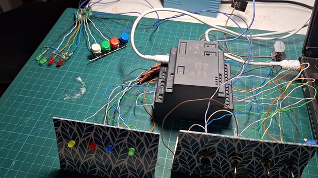
The primary testing field included
Input/Output Operations
I am pleased to confirm that Arduino Opta Micro-PLC demonstrated good performance during testing, with successful results in key areas such as input/output operations, Ethernet communication, and relay switching. The digital I/O, analog inputs, and relay outputs performed reliably and accurately. The communication via Ethernet and Modbus was seamless, making the Opta suitable for integration into existing automation and IIoT systems. Initial problems with PLC IDE have been solved
Arduino IDE was assessed as the primary programming environment for the Arduino Opta in my Roadtest.
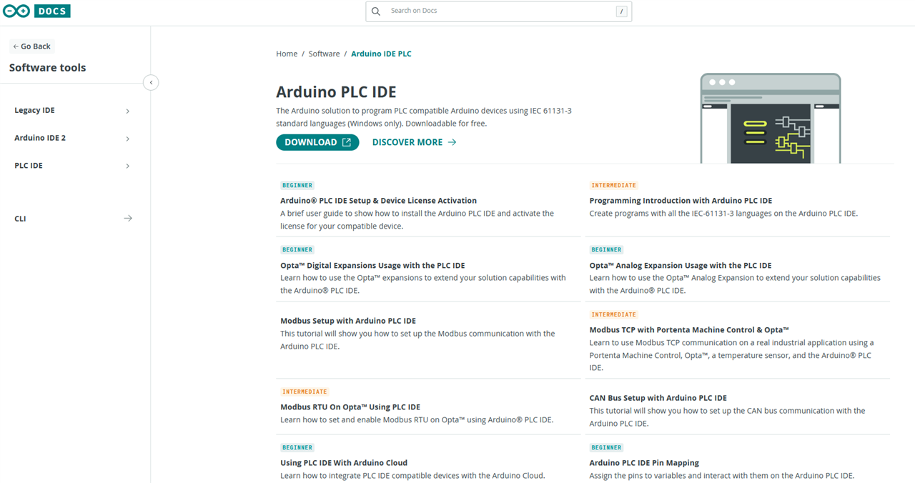
The Arduino IDE (Integrated Development Environment) is a user-friendly software platform used to write, compile, and upload code to Arduino boards.
It supports a wide range of programming languages, primarily Arduino C/C++, and simplifies the process of developing and testing projects by providing a straightforward interface and extensive libraries.
I admit that I have been testing with great pleasure many simple examples included with OPTA libraries in Arduino IDE, in manuals and available on the internet. It took a lot of time but I got to know OPTA very well.
Starting from very basic programming (LED blinking, analog readings, etc.). I went far further through advanced examples involving Ethernet, Modbus RTU, cloud integration, and real-time control.
Regardless of the level of advancement of the tasks,tutorials and examples are easy to follow, well-documented, and mostly error-free.
Tutorials, and Libraries are easy to Use, well supported, and useful
Honestly, I saw that the documentation, manuals, tutorials and shared examples were developing during my roadtest.
The Arduino IDE test stage of my roadtest helped me to evaluate that mostly tutorials and examples from manual effectively help to leverage Opta’s industrial capabilities, including I/O control, Modbus communication, and cloud connectivity.
In this section, I explored various test examples and sample programs developed using the Arduino IDE for the Arduino Opta Micro-PLC. These examples provide hands-on insights into the capabilities of the Opta, demonstrating how its digital and analog I/O, Ethernet connectivity, and Modbus communication can be leveraged for industrial automation and IoT applications. By evaluating these test programs, we will gain a deeper understanding of the device’s functionality, ease of use, and integration potential in real-world scenarios.
To shorten the already too extensive report, I will show my experiences in videos.
Installation of the Arduino IDE and getting started with programs for Arduino Opta Micro-PLC
Video: 03.OPTA.ArduinoIDE
Programmable Inputs and Relays
Simple programs in Arduino IDE implementing Digital Inputs and Digital OutputsArduino Opta Micro-PLC
Digital Inputs
the use of I1, I2, and I3 input terminals as digital inputs

Analog Inputs


You don't have permission to edit metadata of this video.
Video: 04.OPTA.IOs
Ethernet Communication
Web client
Initialize Ethernet with DHCP:
DHCP assigned IP 192.168.1.213
connecting to www.google.com...
connected to 142.250.203.196
HTTP/1.1 200 OK
Web Server
Ethernet WebServer Example
server is at 192.168.2.177
Ethernet WebServer Example
server is at 192.168.1.177
new client
GET / HTTP/1.1
Host: 192.168.1.177
User-Agent: Mozilla/5.0 (Windows NT 10.0; Win64; x64; rv:130.0) Gecko/20100101 Firefox/130.0
Accept: text/html,application/xhtml+xml,application/xml;q=0.9,image/avif,image/webp,image/png,image/svg+xml,*/*;q=0.8
Accept-Language: pl,en-US;q=0.7,en;q=0.3
Accept-Encoding: gzip, deflate
Connection: keep-alive
Upgrade-Insecure-Requests: 1
Priority: u=0, i
client disconnected
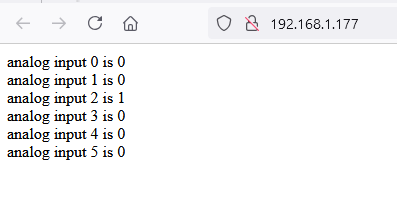
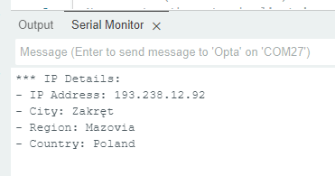
Testing use of the onboard Ethernet PHY transceiver: the Ethernet library
The sketch enables an Opta to connect to the Internet via an Ethernet connection. Once connected, it performs a GET request to the ip-api.com service to fetch details about the device's IP address. It then parses the received JSON object using the Arduino_JSON library to
Extract key IP details: IP address, city, region, and country.
This data is then printed to the Arduino IDE's Serial Monitor.

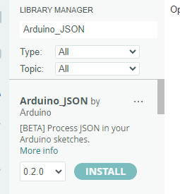
install Arduino_JSON library
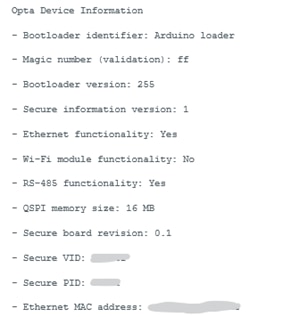
Retrieving the MAC Address of an Opta Device
The Opta micro PLC is designed to operate in several industrial environments involving crucial processes. These processes require controllers to be responsive and precise to manage sensitive tasks and capable of handling large sets of conditions within defined parameters in real-time. Asynchronous operations or spontaneous events are the kind of process that requires immediate attention at a given moment. Therefore, interrupt management is critical to control and optimize these event classes.
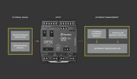
The interrupt, a basic yet vital feature, is available on Opta to handle time-sensitive and unexpected events based on state changes.
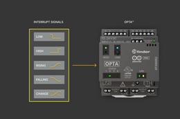

Details in the film below
You don't have permission to edit metadata of this video.
Video: 05.OPTA.Interrupts
At this stage of the test I realized that a large part of Manual Opta is related to full version of The Opta containing WiFi
or the expansion module Arduino Pro Opta Ext D1608E / D1608S
Real-Time Clock (RTC) example runs with WiFi only
Analog RTD Input Mode, also no luck.
The Analog Expansion input channels can be used for temperature metering with PT100 RTDs... but only in external module D1608.
in basic OPTA RTC input isn't available
Arduino Micro-PLC OPTA: 
Expansion Module D1608 
Typically, PLC systems have a modular structure, allowing expansion modules to be connected to the PLC base in various configurations.
In addition to this standard approach, there are also compact PLCs designed for specific and sometimes limited applications.
These controllers integrate a fixed number of I/O and communication modules. However, this doesn’t rule out the possibility of expansion by adding standard modules.
The Arduino Opta Micro-PLC falls into this second category.
I shouldn’t be particularly picky or demanding, but while I understand the limitations of a compact design, I can’t help but miss "on-board" 4–20mA inputs and outputs.
Growing up with the belief that the 4–20mA standard is the most popular in automation systems, its absence feels notable.
Of course, this functionality can be achieved by adding one or more D1608 extension modules. However, doing so significantly increases the overall project cost.
RS-485 Communication Standard
RS-485 is a serial communication standard designed for multi-point systems, making it ideal for industrial environments where devices need to communicate over long distances.
You don't have permission to edit metadata of this video.
Video: 06.OPTA.RS485.1
Overview of Modbus RTU over RS-485
Video: 07.OPTA.RS485.2
Evaluate the ease of integration with third-party PLCs and devices using these protocols.
Assess Modbus libraries and their documentation support in the Arduino IDE.
Ensure smooth data exchange between Arduino Opta and external devices (e.g., external Modbus I/O module).
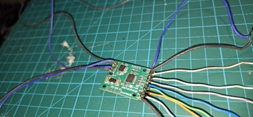
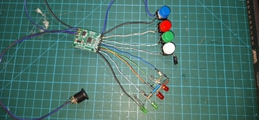
Video: 08.OPTA.Modbus RTU
After a long time of experimenting with Opta programming in Arduino IDE, it was time for a real automation tool - Arduino PLC IDE

You don't have permission to edit metadata of this video.
Video: 09.OPTA.PLC IDE
At the very beginning I experienced problems with the behavior of OPTA and Arduino PLC IDE.
Arduino PLC IDE hung while trying to run OPTA programming
The solution in the film below
Video: 10.OPTA_PLC IDE_faults
And although I still had to perform the memory partitioning procedure in a few cases,
I can admit that the Arduino PLC IDE is an extensive but very convenient tool for programming the OPTA PLC
You don't have permission to edit metadata of this video.
Video: 11.OPTA_PLC IDE_programming
Example of programing in classic automation languages: Ladder, FBD, ST, SFC, and IL of the family of the IEC 61131-3 languages.
Arduino PLC IDE provides all above for easy programming
https://en.wikipedia.org/wiki/IEC_61131-3
Ladder Diagram (LD)
You don't have permission to edit metadata of this video.
Video: 12.OPTA_PLC IDE_Ladder
Function Block Diagram (FBD)
Structured Text (ST)
Sequential Function Chart (SFC)
Instruction List (IL)
You don't have permission to edit metadata of this video.
Video: 13.OPTA_PLC IDE_FBD
Using Arduino PLC IDE for Modbus RTU projects
You don't have permission to edit metadata of this video.
Video: 14.OPTA_PLC IDE_Modbus
GO TO SCADA
Project of implementation of Arduino Cloud in Opta
You don't have permission to edit metadata of this video.
Video: 15.OPTA_Arduino_Cloud
Supervisory Control and Data Acquisition (SCADA) and Industrial Internet of Things (IIoT) are two crucial technologies in modern industrial automation and control systems. Both technologies have similar objectives—monitoring, controlling, and optimizing industrial processes—but differ significantly in their architecture, capabilities, and implementation. Here's a detailed comparison of SCADA vs. IIoT:
Communication Protocols
Data Handling and Analytics
Scalability
Control vs. Data Analytics
Both SCADA and IIoT are critical technologies for industrial control, but they have different strengths:
While SCADA remains essential for legacy industrial systems requiring high control fidelity, IIoT is the next frontier, offering enhanced flexibility, intelligence, and the ability to connect and analyze vast amounts of industrial data. Many industries are gradually transitioning from traditional SCADA systems to IIoT-driven architectures, leveraging the strengths of both technologies for optimal performance and efficiency.
Assess which system (SCADA or IoT) is more suitable for certain types of industrial applications.
Evaluate scalability, maintenance, and data storage needs.
When evaluating SCADA versus IoT (IIoT) for industrial applications, it's important to consider the nature of the application, scalability, maintenance needs, and data storage requirements. Both systems have strengths in specific areas, but their suitability depends on factors such as the size of the operation, the level of automation, data processing needs, and the type of industry.
The Arduino Opta Micro-PLC stands out in the industrial automation market, offering a unique blend of flexibility, real-time performance, security, and ease of use. To provide a comprehensive evaluation, let's compare the Arduino Opta with some of its notable competitors in the Micro-PLC and Industrial IoT (IIoT) space, such as:
The Arduino Opta Micro-PLC offers superior flexibility, IoT connectivity, and advanced security features compared to many competitors. It is especially strong in cloud-based applications and real-time control, making it an ideal solution for Industry 4.0 and IIoT environments. While Siemens LOGO!, Rockwell Micro800, and Schneider Modicon M221 provide strong industrial functionality, Opta leads in ease of use, cloud integration, and security, making it a standout choice for future-proof automation systems.
When comparing the Arduino Opta Micro-PLC to its competitors, it is important to evaluate both initial costs and the potential long-term savings in terms of ease of programming, maintenance, scalability, and integration. While initial cost is a key factor in any decision, long-term operational and maintenance savings can greatly influence the overall value proposition of the system.
Arduino Opta Micro-PLC offers excellent value for small to medium-sized industrial applications, particularly for those requiring IoT capabilities and cloud-based integration. Its lower initial cost, combined with ease of programming, Arduino ecosystem integration, and advanced IoT features, makes it a highly attractive option for long-term savings. Remote monitoring and OTA firmware updates can greatly reduce maintenance costs over time.
This report summarizes my RoadTesting and evaluation of the Arduino Opta Micro-PLC.
The work began with an overview of the PLC, including a review of available documentation, manuals, and examples, followed by an analysis of its technical design and components. I conducted several tests and ran numerous examples, starting with the Arduino IDE and progressing to the Arduino PLC IDE. My focus included I/O communication, RS485, and Modbus RTU integration with external devices. Finally, I developed a project utilizing the Arduino Opta PLC with Arduino Cloud.
Despite encountering several challenges, particularly with the Arduino PLC IDE freezing, these issues were resolved, I greatly appreciate the Opta PLC for its ease of startup and programming, its universality, and its flexibility in adapting to various applications.
Working with the Arduino Opta has been an OPTA-mistic experience—so many possibilities in automation!
I extend my gratitude to the project sponsors and apologize for the significant delay in completing this Roadtest.
