RoadTest: Seeking an Electronics Engineer to Evaluate a Broadcom Optical Wireless Transceiver Kit
Author: JWx
Creation date:
Evaluation Type: Evaluation Boards
Did you receive all parts the manufacturer stated would be included in the package?: True
What other parts do you consider comparable to this product?: none found - possibly optical serial interfaces, but with much lower bandwidth
What were the biggest problems encountered?: lack of more detailed documentation
Detailed Review:
Broadcom AFBR-FSEK50B00E Optical Transceiver is an free space communications module, allowing for high-speed, bidirectional, wireless communication at short (30-100mm) distances using IR laser radiation.
It consists of transmiter part, based on vertical cavity surface-emitting laser (VCSEL) with a driving circuit and a receiver, consisting of PIN photodiode with transimpedance amplifier and signal conditioning circuit.
On top of it there is a set of coaxial lens, giving it full 360° rotation working angle and Laser Class 1 classification, which ensures that it is safe when observed by naked eye or typical magnifying optics
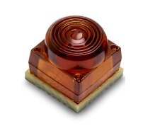
Transceiver is designed to work for data rates between 125 Mb/s and 5 Gb/s over 0 °C - 85 °C temperature range and with power consumption of about 120 mW (powered by 3.3 V power supply and consuming no more than 8.5 mA by the transmitter and 26 mA by the receiver).
Suggested application areas include:
Documentation provides maximum allowed misalignment curve for 5 Gb/s transfer rate and bit error rate of 10-9
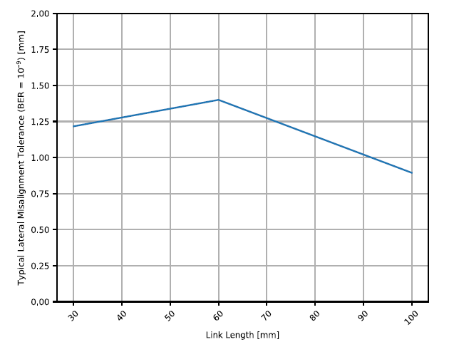
which could be useful when evaluating the possibility of use this part in a given mechanical (for example: rotating) setup. As can be seen, some precision is needed when establishing a link.
To better evaluate the transceiver parameters, two kinds of evaluation kits are offered:
In this roadtest, we will evaluate Ethernet version of the evaluation kit (AFBR-FSEK50B00E).
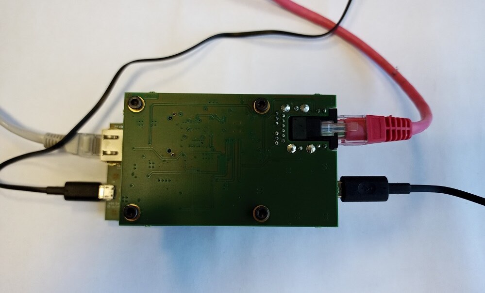
The kit consists of four boards - two for the each side of the optical link: one optical transceiver board and one media converter board:
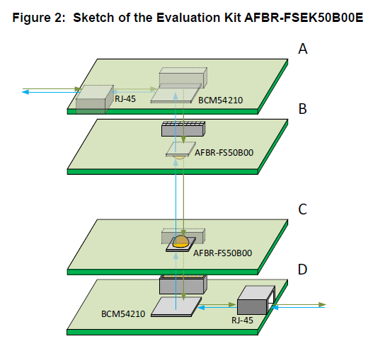
with each side providing one RJ-45 data connector and micro USB power connector.
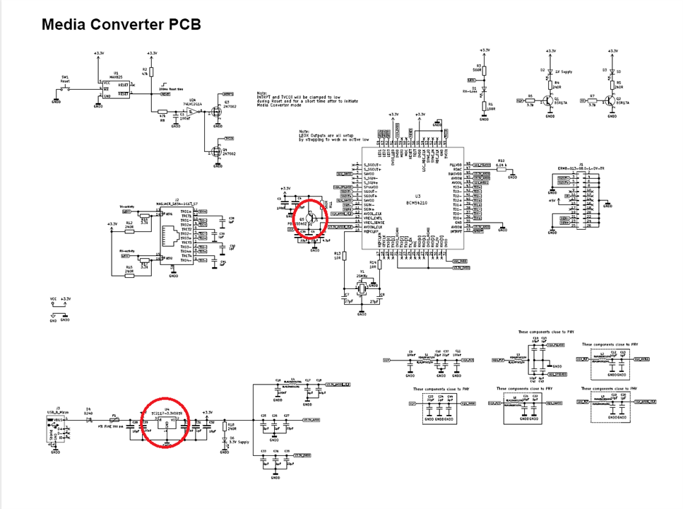
Media converter board includes BCM54210 Ethernet PHY configured as a standalone media converter, working as a bridge between 1000BASE-T (copper) and 1000BASE-X (optical) interface.
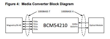
Unfortunately, no detailed documentation of this part is publicly available, so it has to be used "as is" despite it's many interesting features.
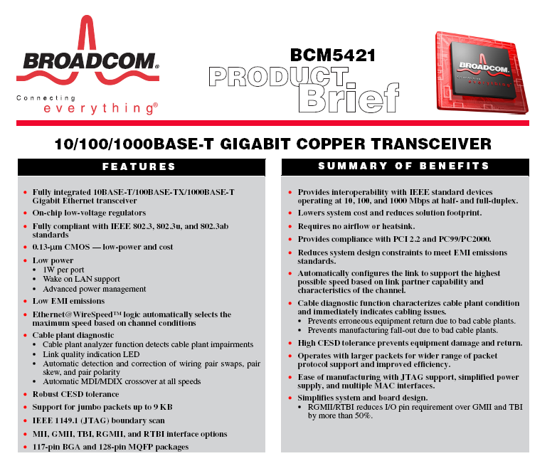
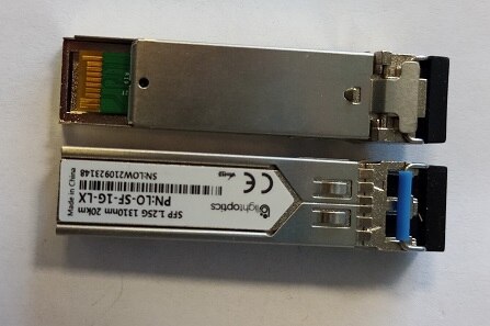
Block schematics of the media converter seems to confirm the observation that AFBR-FS50B00 module can be used in place of standard SFP (small form-factor pluggable ) transceiver, like ones below
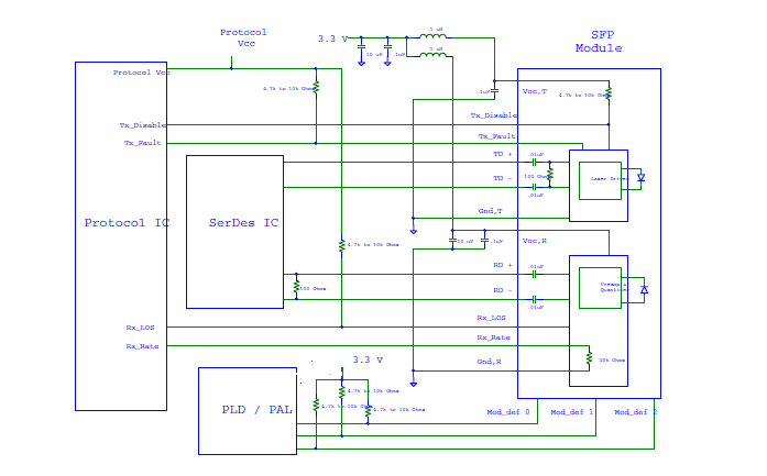
This theory is reinforced by the block diagram of SFP interface as specified by INF-8074i specification:
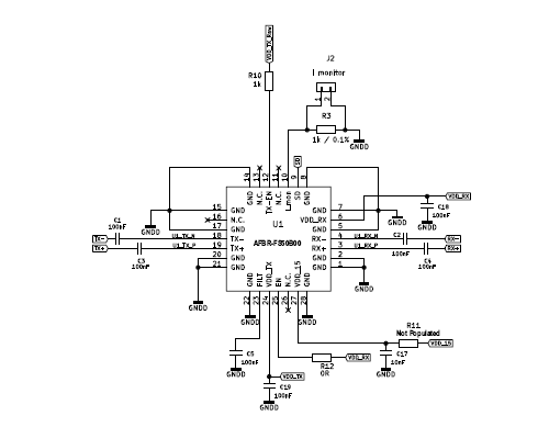
that is very similar to the AFBR-FSEK50B00E optical frontend electrical interface:
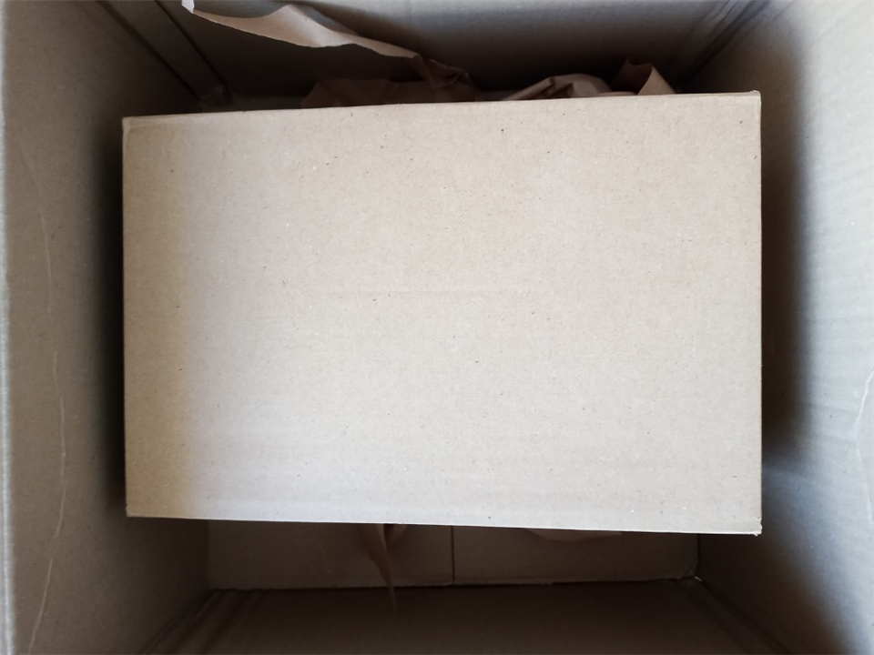
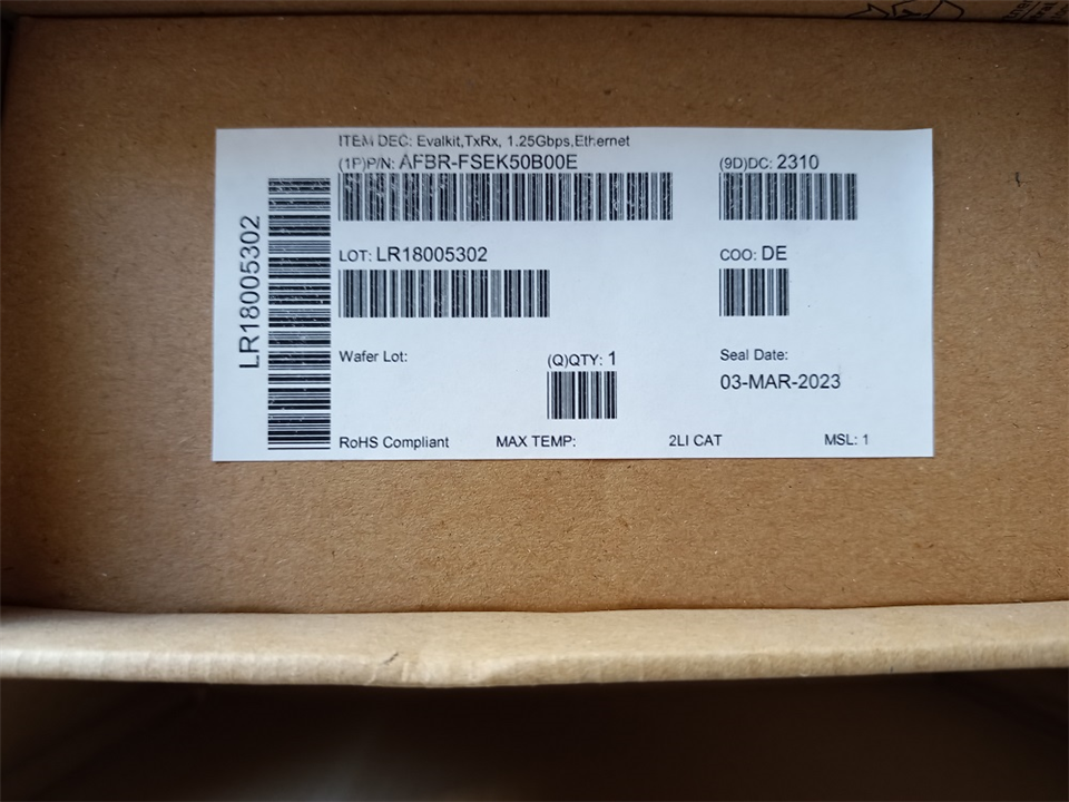
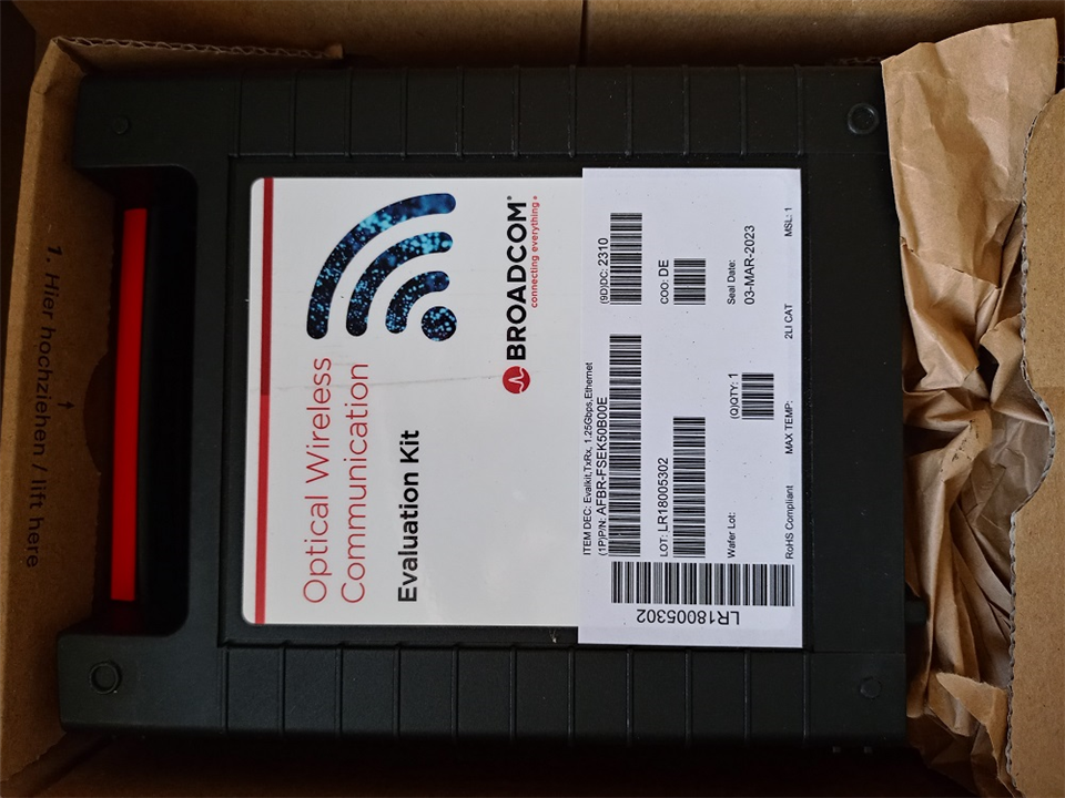
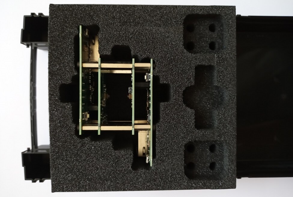
Module has arrived securely packaged in a cardboard box that contained elegant plastic enclosure filled with a foam that was holding evaluation kit in place. No additional accessories were included, but - in fact - none are needed: the kit can be connected using two standard Ethernet cables and two micro USB cables for power.
| {gallery}unboxing |
|---|
|
Outer cardboard box |
|
Inner cardboard box |
|
Plastic kit enclosure |
|
The kit inside foam filling |
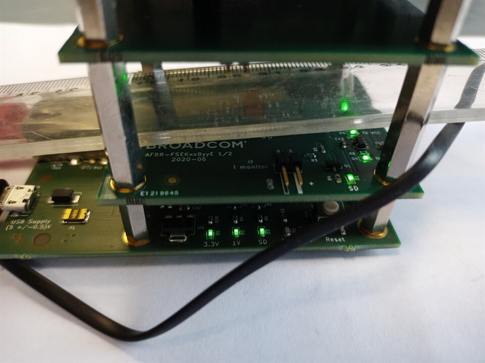
Evaluation kit is built as a four PCB "sandwich", with external screws dual-purposed as module's feet
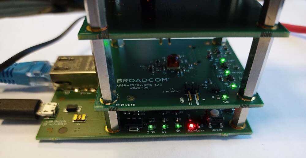
Media converter board has four LEDs - two of them indicate presence of 3.3V and 1V supply voltages, SD LED turns green when optical signal is present and Rx Loss LED turns red when copper interface is down.
As there is no auto-negotiation on the optical link, Rx Loss is also reported when connected to the link not supporting 1Gb/s speed (for example 100BASE-T interface) - despite the fact that the transceiver supports signal speeds from 125Mb/s - so some care needs to be taken when selecting test equipment to use interfaces capable of operating at 1Gb/s.
Another important note is that media converters seem to propagate "link down" condition across the link, so the datasheet advises against powering up both boards simultaneously and states that in such a situation link might not be established. At least one second wait in powering up sequence is advised.
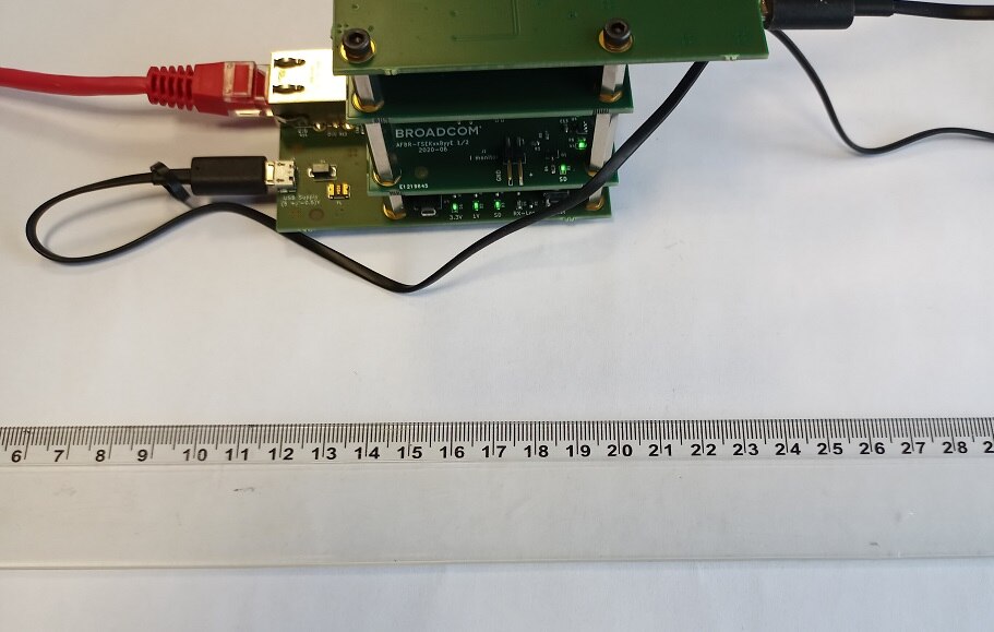
Another thing that can be visually identified is an optical link length that seems too short.
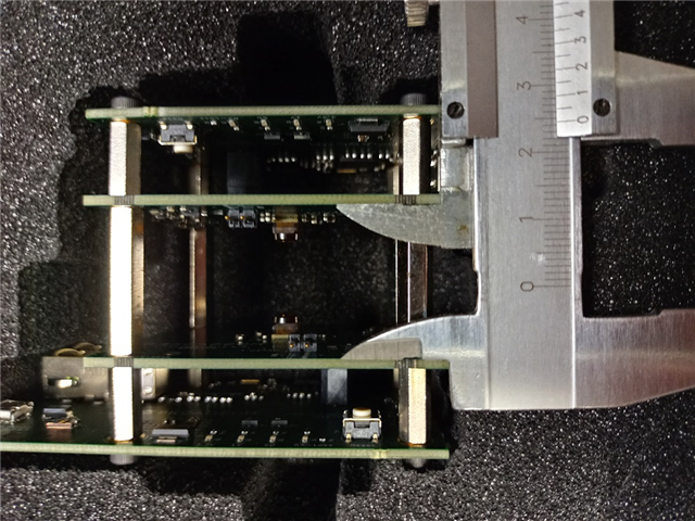
As - according to the documentation - link length is defined as "top of lens to top of lens" distance and the transceiver is 4.83 mm high, calculated link length is
24.5 mm - 2*4.83 mm = 14.84 mm
which is much lower than the specified range of 30 - 100 mm.
After powering up, media converter board draws following current from the USB port:
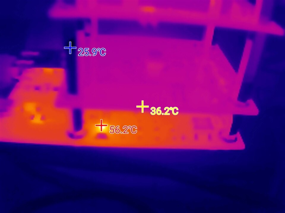
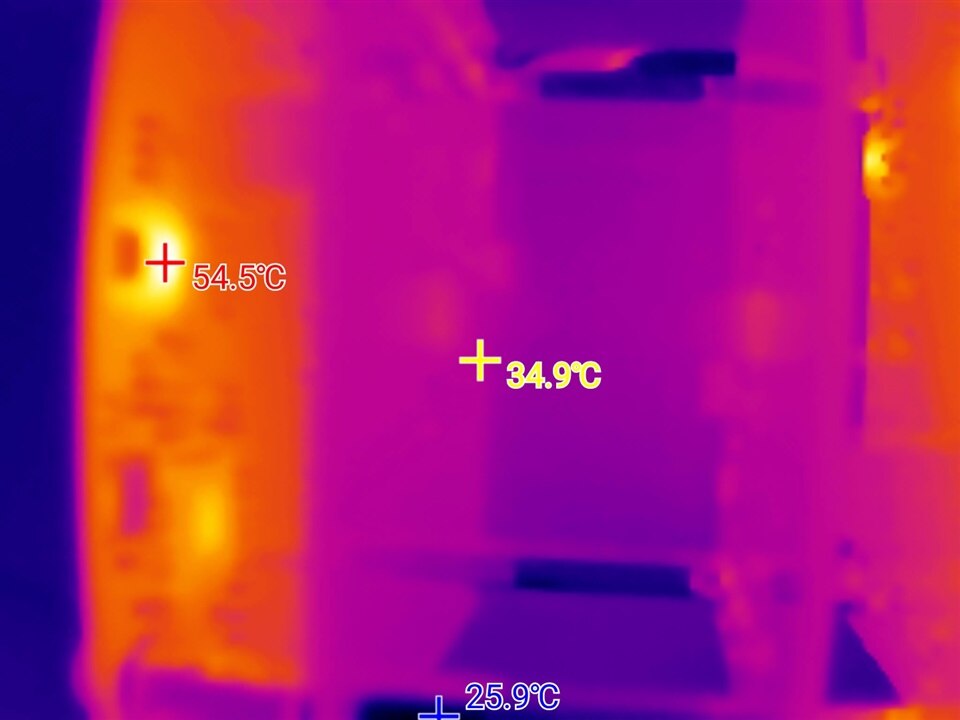
That is significantly more than expected 35 mA of the transceiver. Additionally, media converter boards are getting warm when powered, indicating where most of the power consumption occurs:
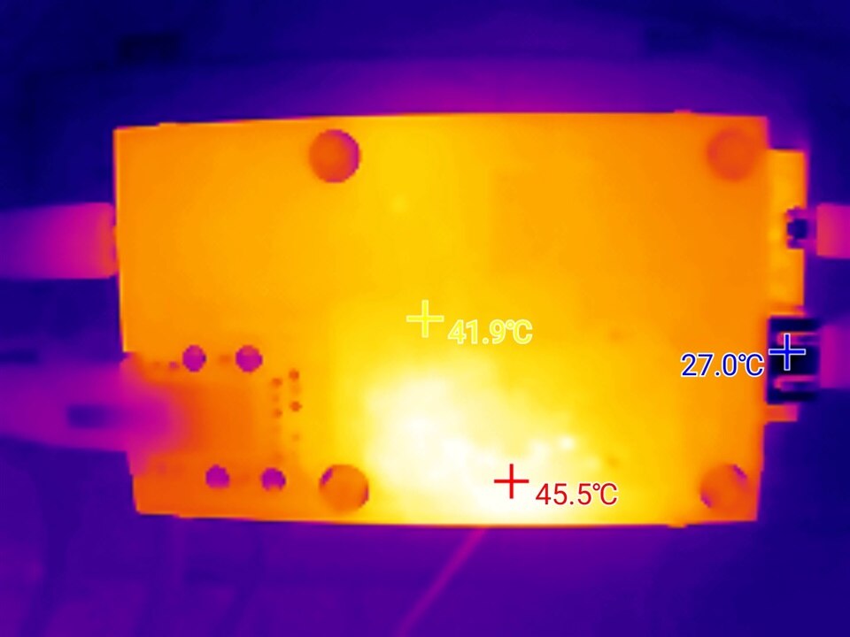
two additional photos pinpoint power consumption areas as linear regulators: one (U4) for 3.3V rail and another one as power transistor driven by the 1V regulator inside PHY (Q5)
| {gallery}thermal distribution |
|---|
|
3.3V LDO |
|
Q5 power transistor |
As can be seen - elevated power consumption is not connected with the transceiver operation but mainly with media converter design.
To evaluate the performance of the optical modules, test setup was prepared. It consisted of two 1000Base-T Ethernet (a.k.a. copper Gigabit Ethernet) NICs installed in two GNU/Linux servers.
The cards were of different types:
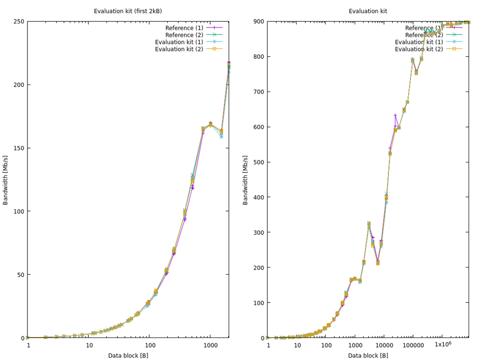
Reference tests were conducted using Netpipe TCP module, that is providing detailed link bandwidth measurement by sending blocks of different size using ping-pong technique. This measurement provided following baseline (X axis represents block size in bytes, Y axis transfer in Mb/s), with two measurements from each link to check repeatability:
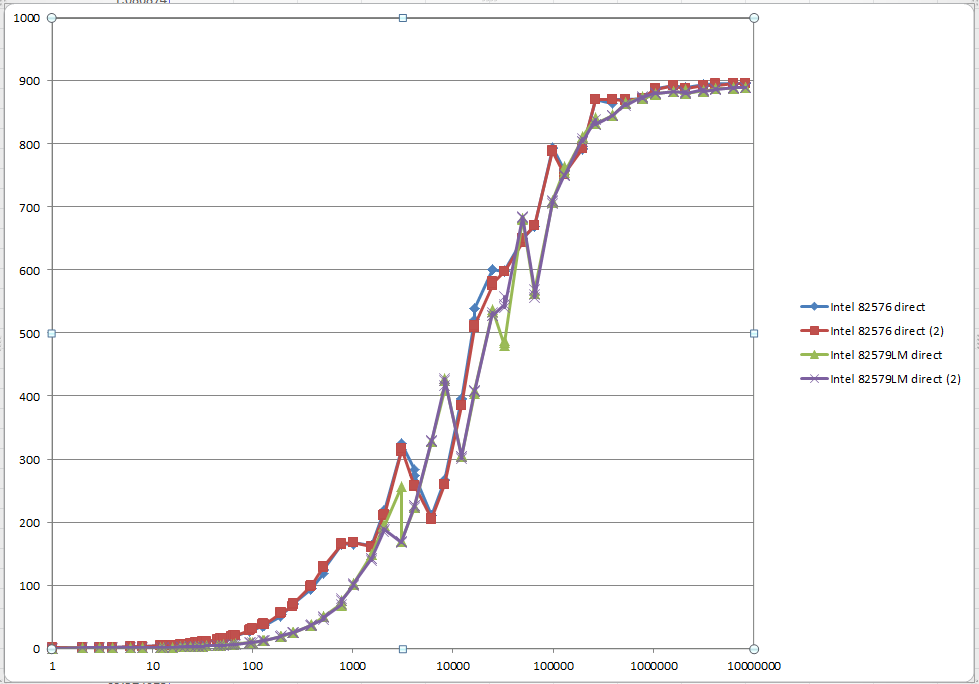
As can be seen both adapters achieve almost full 1Gb/s bandwidth for large blocks, but initially data transfer is limited by the transmission delay (which is more than three times longer for 82579LM) . Additionally, for some block sizes transfer rate degradation is observed. Difference of performance for small blocks can be better seen on the following graph fragment, when 82576 achieves more than 60% faster transfer than 82579LM.
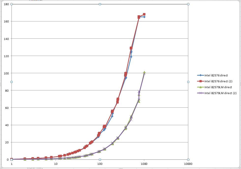
Rest of the testing was conducted using more performant (but also more quirky - where more events of performance regression for different block sizes were observed) Intel 82576 card.
First, direct connection was tested:
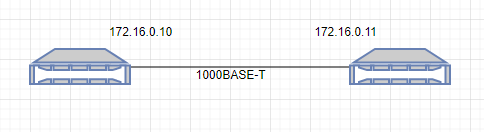
# ping 172.16.0.11PING 172.16.0.11 (172.16.0.11) 56(84) bytes of data.
64 bytes from 172.16.0.11: icmp_seq=1 ttl=64 time=0.165 ms
64 bytes from 172.16.0.11: icmp_seq=2 ttl=64 time=0.200 ms
64 bytes from 172.16.0.11: icmp_seq=3 ttl=64 time=0.180 ms
64 bytes from 172.16.0.11: icmp_seq=4 ttl=64 time=0.174 ms
64 bytes from 172.16.0.11: icmp_seq=5 ttl=64 time=0.189 ms
64 bytes from 172.16.0.11: icmp_seq=6 ttl=64 time=0.192 ms
Then Iperf3 test was performed using TCP protocol
#iperf3 -c 172.16.0.11
Connecting to host 172.16.0.11, port 5201
[ 5] local 172.16.0.10 port 38908 connected to 172.16.0.11 port 5201
[ ID] Interval Transfer Bitrate Retr Cwnd
[ 5] 0.00-1.00 sec 114 MBytes 957 Mbits/sec 0 392 KBytes
[ 5] 1.00-2.00 sec 112 MBytes 942 Mbits/sec 0 392 KBytes
[ 5] 2.00-3.00 sec 112 MBytes 942 Mbits/sec 0 392 KBytes
[ 5] 3.00-4.00 sec 112 MBytes 941 Mbits/sec 0 392 KBytes
[ 5] 4.00-5.00 sec 112 MBytes 939 Mbits/sec 0 392 KBytes
[ 5] 5.00-6.00 sec 112 MBytes 940 Mbits/sec 0 392 KBytes
[ 5] 6.00-7.00 sec 113 MBytes 946 Mbits/sec 0 392 KBytes
[ 5] 7.00-8.00 sec 112 MBytes 940 Mbits/sec 0 392 KBytes
[ 5] 8.00-9.00 sec 112 MBytes 941 Mbits/sec 0 392 KBytes
[ 5] 9.00-10.00 sec 112 MBytes 940 Mbits/sec 0 392 KBytes
- - - - - - - - - - - - - - - - - - - - - - - - -
[ ID] Interval Transfer Bitrate Retr
[ 5] 0.00-10.00 sec 1.10 GBytes 943 Mbits/sec 0 sender
[ 5] 0.00-10.04 sec 1.10 GBytes 938 Mbits/sec receiver
Followed by UDP protocol
# iperf3 -c 172.16.0.11 -u -b 1000M
Connecting to host 172.16.0.11, port 5201
[ 5] local 172.16.0.10 port 60287 connected to 172.16.0.11 port 5201
[ ID] Interval Transfer Bitrate Total Datagrams
[ 5] 0.00-1.00 sec 114 MBytes 956 Mbits/sec 82534
[ 5] 1.00-2.00 sec 114 MBytes 956 Mbits/sec 82563
[ 5] 2.00-3.00 sec 114 MBytes 956 Mbits/sec 82562
[ 5] 3.00-4.00 sec 114 MBytes 956 Mbits/sec 82563
[ 5] 4.00-5.00 sec 114 MBytes 956 Mbits/sec 82562
[ 5] 5.00-6.00 sec 114 MBytes 956 Mbits/sec 82563
[ 5] 6.00-7.00 sec 114 MBytes 956 Mbits/sec 82563
[ 5] 7.00-8.00 sec 114 MBytes 956 Mbits/sec 82562
[ 5] 8.00-9.00 sec 114 MBytes 956 Mbits/sec 82563
[ 5] 9.00-10.00 sec 114 MBytes 956 Mbits/sec 82563
- - - - - - - - - - - - - - - - - - - - - - - - -
[ ID] Interval Transfer Bitrate Jitter Lost/Total Datagrams
[ 5] 0.00-10.00 sec 1.11 GBytes 956 Mbits/sec 0.000 ms 0/825598 (0%) sender
[ 5] 0.00-10.04 sec 1.11 GBytes 952 Mbits/sec 0.011 ms 0/825563 (0%) receiver
So far, so good - no packet loss was recorded and data transfer rate is good.
Then, evaluation module was inserted between the hosts
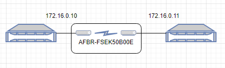
and tests were repeated
# ping 172.16.0.11
PING 172.16.0.11 (172.16.0.11) 56(84) bytes of data.
64 bytes from 172.16.0.11: icmp_seq=1 ttl=64 time=0.149 ms
64 bytes from 172.16.0.11: icmp_seq=2 ttl=64 time=0.187 ms
64 bytes from 172.16.0.11: icmp_seq=3 ttl=64 time=0.182 ms
64 bytes from 172.16.0.11: icmp_seq=4 ttl=64 time=0.177 ms
64 bytes from 172.16.0.11: icmp_seq=5 ttl=64 time=0.170 ms
64 bytes from 172.16.0.11: icmp_seq=6 ttl=64 time=0.195 ms
Iperf3 test was performed using TCP protocol
# iperf3 -c 172.16.0.11
Connecting to host 172.16.0.11, port 5201
[ 5] local 172.16.0.10 port 50024 connected to 172.16.0.11 port 5201
[ ID] Interval Transfer Bitrate Retr Cwnd
[ 5] 0.00-1.00 sec 114 MBytes 959 Mbits/sec 0 390 KBytes
[ 5] 1.00-2.00 sec 112 MBytes 942 Mbits/sec 0 390 KBytes
[ 5] 2.00-3.00 sec 112 MBytes 942 Mbits/sec 0 390 KBytes
[ 5] 3.00-4.00 sec 111 MBytes 935 Mbits/sec 0 390 KBytes
[ 5] 4.00-5.00 sec 112 MBytes 942 Mbits/sec 0 390 KBytes
[ 5] 5.00-6.00 sec 112 MBytes 942 Mbits/sec 0 390 KBytes
[ 5] 6.00-7.00 sec 112 MBytes 942 Mbits/sec 0 390 KBytes
[ 5] 7.00-8.00 sec 112 MBytes 942 Mbits/sec 0 390 KBytes
[ 5] 8.00-9.00 sec 112 MBytes 942 Mbits/sec 0 390 KBytes
[ 5] 9.00-10.00 sec 112 MBytes 942 Mbits/sec 0 390 KBytes
- - - - - - - - - - - - - - - - - - - - - - - - -
[ ID] Interval Transfer Bitrate Retr
[ 5] 0.00-10.00 sec 1.10 GBytes 943 Mbits/sec 0 sender
[ 5] 0.00-10.04 sec 1.10 GBytes 938 Mbits/sec receiver
And UDP protocol
# iperf3 -c 172.16.0.11 -u -b 1000M
Connecting to host 172.16.0.11, port 5201
[ 5] local 172.16.0.10 port 56709 connected to 172.16.0.11 port 5201
[ ID] Interval Transfer Bitrate Total Datagrams
[ 5] 0.00-1.00 sec 114 MBytes 956 Mbits/sec 82534
[ 5] 1.00-2.00 sec 114 MBytes 956 Mbits/sec 82563
[ 5] 2.00-3.00 sec 114 MBytes 956 Mbits/sec 82563
[ 5] 3.00-4.00 sec 114 MBytes 956 Mbits/sec 82562
[ 5] 4.00-5.00 sec 114 MBytes 956 Mbits/sec 82563
[ 5] 5.00-6.00 sec 114 MBytes 956 Mbits/sec 82562
[ 5] 6.00-7.00 sec 114 MBytes 956 Mbits/sec 82563
[ 5] 7.00-8.00 sec 114 MBytes 956 Mbits/sec 82563
[ 5] 8.00-9.00 sec 114 MBytes 956 Mbits/sec 82563
[ 5] 9.00-10.00 sec 114 MBytes 956 Mbits/sec 82562
- - - - - - - - - - - - - - - - - - - - - - - - -
[ ID] Interval Transfer Bitrate Jitter Lost/Total Datagrams
[ 5] 0.00-10.00 sec 1.11 GBytes 956 Mbits/sec 0.000 ms 0/825598 (0%) sender
[ 5] 0.00-10.04 sec 1.11 GBytes 952 Mbits/sec 0.020 ms 0/825573 (0%) receiver
Very good results - no packet loss was recorded and the bandwidth was very similar to the direct connection setup.
Finally, Netpipe test provided results as below - transmission rate curve when using evaluation kit is hard to distinguish from direct copper connection.
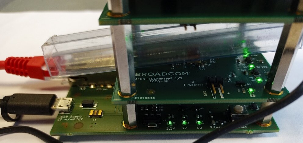
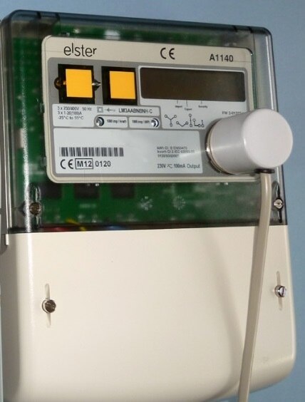
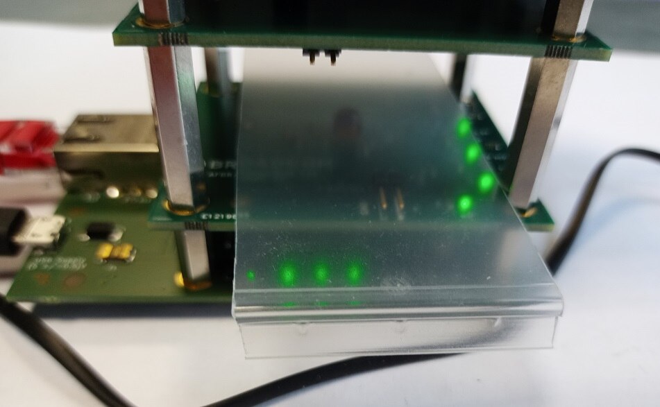
Following test cases take into consideration the fact that unobstructed data channel is sometimes hard to obtain. For example, in the setup as on the photo below - optical interface is connected to the equipment, providing isolation without creating weak spots like connectors that can get dirty, damaged or become point of water or humidity ingress. Unfortunately, all the benefits of such a connection would be lost if enclosure wall (or dirty/scratched enclosure wall) would hinder the optical communication.
To test the influence of different types of materials in the optic link, several tests were devised.
For every scenario, two test runs were performed and then compared to two series of reference data - this approach was adopted to detect possible differences between test runs.
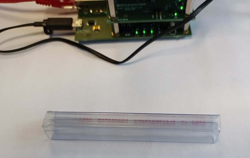
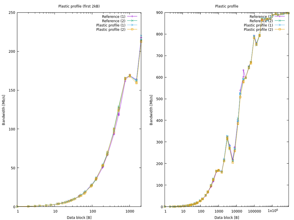
As a mock-up of typical window glass (with at least two glass panels separated by the air gap), plastic profile (commonly used to store DIP chips) was used.
| {gallery}Plastic profile |
|---|
|
Plastic profile |
|
Profile under test |
Plastic profile test was passed without observable signal degradation - in fact, signal quality is hard to distinguish from the direct connection.
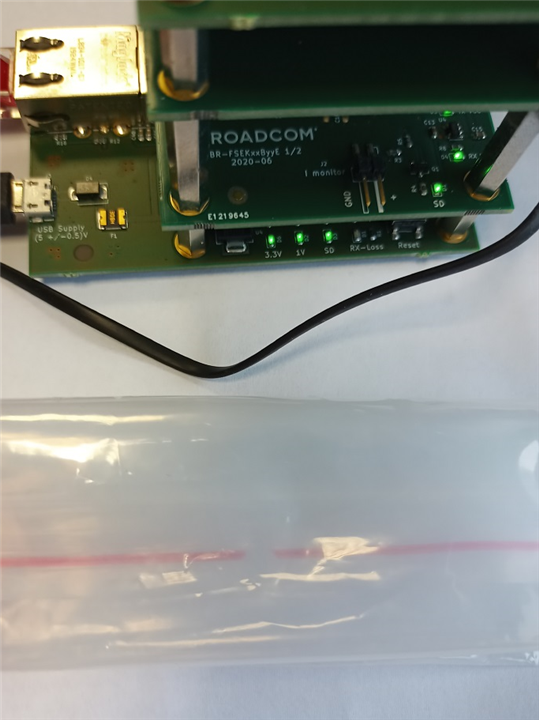
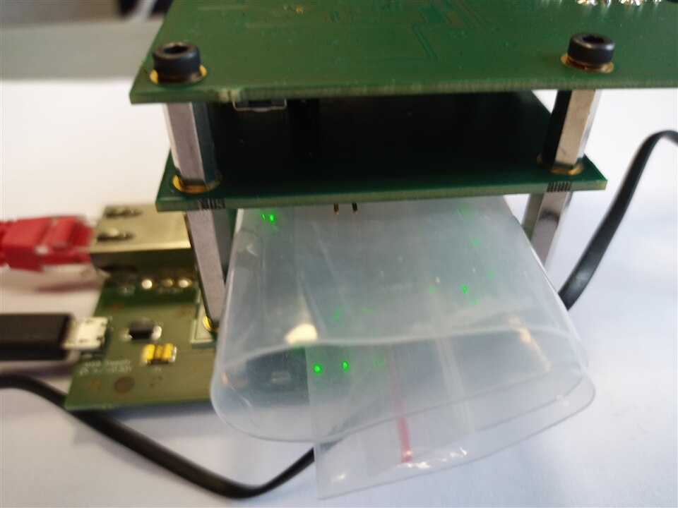
As plastic profile test was successful, let's find something with even more glossy surfaces, possibly creating more reflections - something like a string bag
| {gallery}String bag |
|---|
|
Another reflective plastic test case |
|
Under test |
This one was more challenging - depending on the bag placement and number of folds, transfer was either not possible or was pretty good:
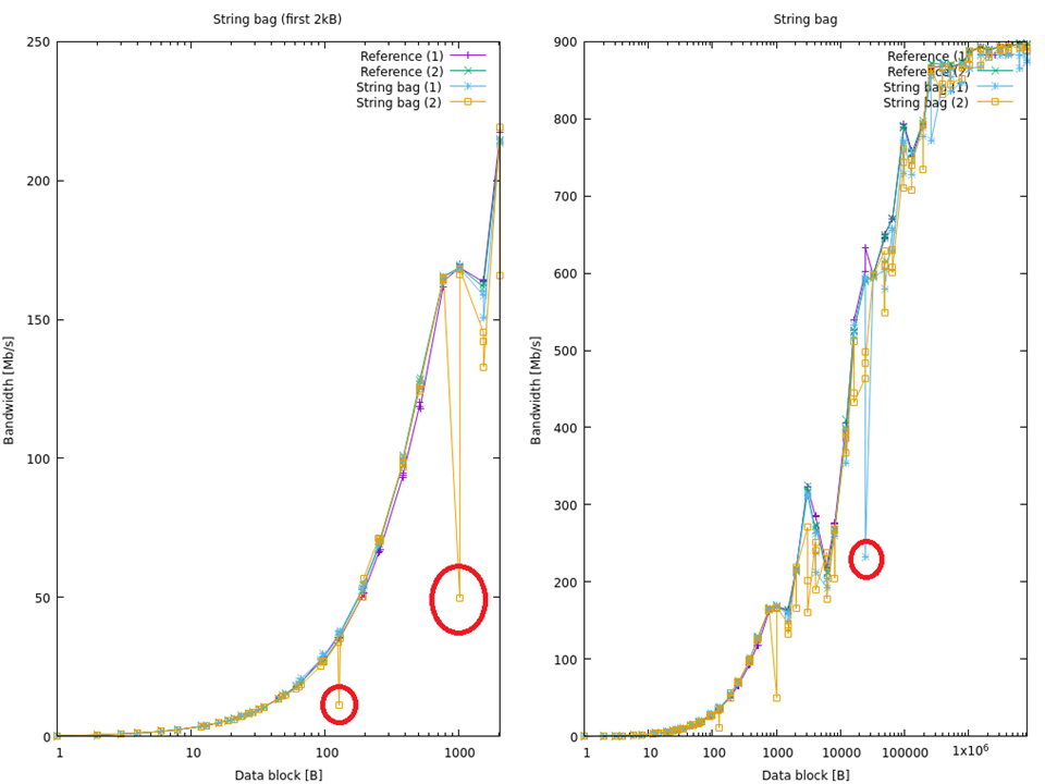
As can be seen - overall test result was ok, but some packet loss was detected (visible on the plot when only one of two data series had momentary performance degradation, indicating TCP retransmission caused by packet loss).
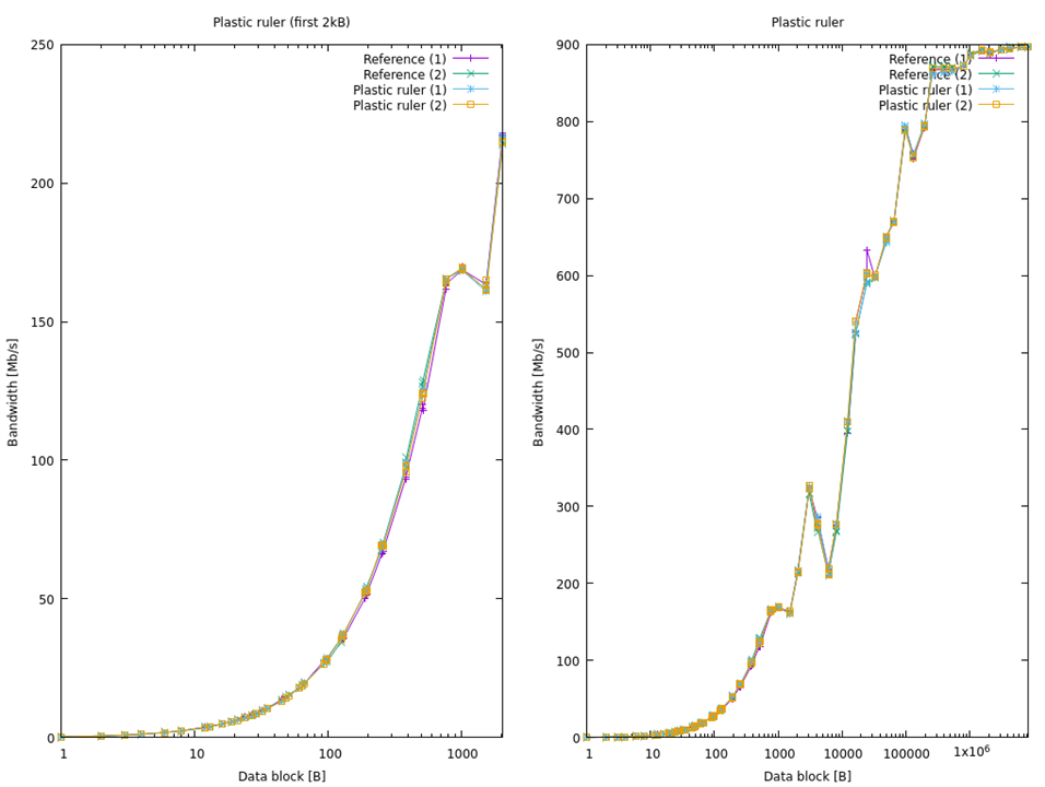
What's about thicker plastic element? Like a transparent enclosure wall? Let's see
| {gallery}Plastic ruler |
|---|
|
Thicker plastic element |
|
Under test |
As can be seen, transparent plastic element about 2mm thick is not creating observable signal quality degradation in this test.
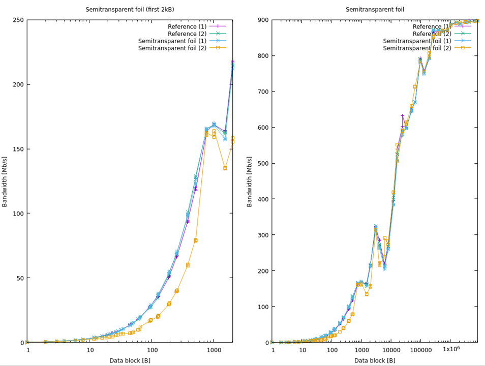
And what will happen if our obstacle will be not fully transparent?
This one is really interesting - one data series has performance similar to the direct connection and another exhibits noticeably longer transmission delay (for small data blocks) but without visible data loss symptoms.
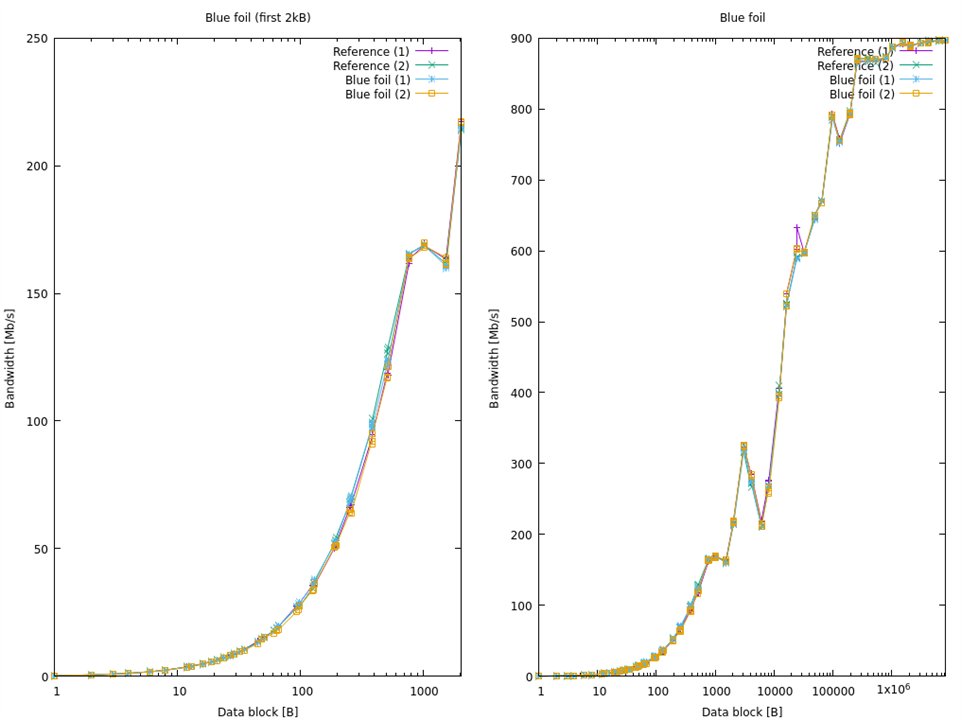
To this point we were testing transparent or semi-transparent obstacles. Let's see what will happen when our obstacle will be of different color - for example blue (not expected to attenuate IR radiation)
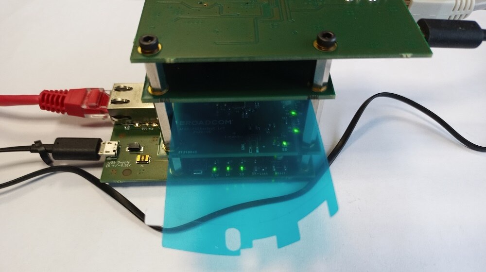
As can be seen - nothing spectacular had happened - transfer rate is again very similar to the direct connection.
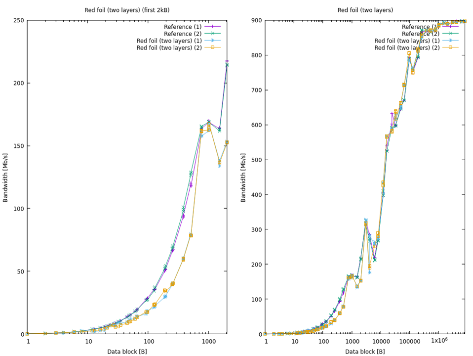
If previous one was working that good, let's see what will happen when red (possibly attenuating IR signal) foil is used?
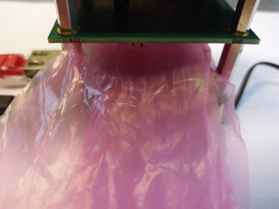
This test was conducted in two parts: first test iteration was conducted using double layer of red foil and resulted in consistent increase of transmission delay for both test series (as seen on the plot below). Trying to repeat the test using three layers of the foil resulted in a very high packet loss, preventing the benchmark from completing - possibly attenuation was too high to establish a reliable link.
AFBR-FS50B00 seems to be very capable optical interface for short-range free space (or not-exactly-free-space as we have learned) links, allowing for all sorts of temporary and not physically connected interfaces. Some care should be exercised to precisely put both interfaces in line, especially for temporary setups, because misalignment of more than 1 - 1.5 mm is considered problematic for high speeds and expected low bit error rate. In some use cases temperature range starting from 0°C could be somewhat limiting.
Gigabit Ethernet evaluation kit allows for a very quick deployment of the transceiver by allowing it to interface to the standard and inexpensive copper gigabit Ethernet equipment. Its compact design resulting in shorter than specified optical link length is not hindering the attainable speed and link quality. Somewhat problematic is a lack of detailed documentation that is limiting the possibility to understand some of the edge cases - for example, increased link latency (but no visible packet loss) in cases of increased optical signal attenuation seems to be linked with media converter operation, but nothing more solid can be said without additional data.