RoadTest: Test out the Raspberry Pi Compute Module 5 Development Kit!
Author: s1m0n3t
Creation date:
Evaluation Type: Development Boards & Tools
Did you receive all parts the manufacturer stated would be included in the package?: True
What other parts do you consider comparable to this product?: Raspberry Pi 5
What were the biggest problems encountered?: Limited USB ports
Detailed Review:
This RoadTest set out to answer a specific question: can I use a Raspberry Pi CM5 as a core element for an instrument, on my bench, which looks like a real tool?
Let's be honest, most of the RPi-based projects that you can find online are always in a messy breadboard style, with cables, jumpers and small modules running around.
Spoiler: you won't see something so different from that in this article! At least not at this stage.
But what I like about the concept of the Compute Module version of the Raspberry Pi is that you can start with a development board and, after a proof of concept is completed, you can easily turn it into a product. Because the IO board provided with this kit is really handy to go straightforward into the development phase, but at the end it's just an interface board. When your application is ready, you can design a custom PCB for your own application and plug in only the small Compute Module.
As an electronic engineer and PCB designer, I really love this approach!
So...if you agree with me, I would skip the "unboxing" and "what's included" part, which you will probably find from other RoadTesters and it won't have any added value from my side, so we can go straight to the point.
I'm approaching the radioamateur world, and I was looking for a scanner, in other words a broad band receiver, which today can be easier and cheaper with SDR (Software Defined Radio). You can easily find RTL-SDR dongles that does this job for a cheap price. I recently bought a Nooelec NESDR SMArt v5, which can receive from 24 MHz to 1.7GHz and optionally down to 0.1 MHz with direct sampling. You can plug it in your PC and use one of the free software tools to use it. But I wanted to transform it into a standalone receiver, somehow comparable to a more expensive desktop radio receiver.
Can I do it with this RPi CM5? Let's find out...
One of the differences between a Raspberry Pi 5 in its classic form factor and a Compute Module is that this one include an eMMC memory, so you don't need to install the OS on an external SD card. This makes it more reliable for a long lasting device, due to the limited writing cycles of an SD card. But the initial flashing is just a bit more tricky:
I just summarized the steps, but please refer to the official guide, where you can find different instructions if you use Linux, Windows or Mac:
https://www.raspberrypi.com/documentation/computers/compute-module.html#flash-compute-module-emmc
After the initial setup, if you set your home network info as well, I find convenient interacting with the RPi via SSH from my PC, instead of connecting a monitor, a keyboard and a mouse to directly control it.
I found convenient to power the RPi with a standard USB-C, but it's not recommended to use a standard 5V/2A (or even 1A) power supply. It's better to use the provided power supply, that can provide up to 5A, or an USB PD power supply, like I did.
But let's see the actual power consumption. I used an USB-C power meter to check the actual voltage and current during each phase:
| Status | Voltage | Current | Power | Temperature |
| OS running, Wi-Fi ON, no device attached | 5.075 V | 0.298 A | 1.512 W | 36.7 C |
| CPU stress test (5 min, open case) | 4.989 V | 1.128 A | 5.628 W | 54.9 C |
| CPU stress test (5 min, closed case) | 4.982 V | 1.184 A | 5.901 W | 63.1 C |
| SDR application | 4.889 V | 2.087 A | 10.203 W | 46.2 C |
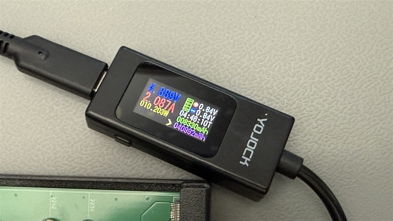
Notes:
For the CPU stress test I used the command stress-ng --cpu 4 (to be installed with apt-install stress-ng -y).
I measured the temperature with the internal sensor, using the command vcgencmd measure_temp. You can use watch -n 1 vcgencmd measure_temp in another window, if you want to constantly monitor it.
After the first 2 measurements with the case open and the fan disconnected, I connected the fan and closed the case. I was actually expecting a lower temperature, due to the forced ventilation, but it was actually higher. The fan is really small and not aligned with the heatsink, so not really efficient. But if the max temperature is around 65 degrees Celsius at the CPU max load, it's really acceptable.
For my SDR application (spoiler, for power and temperature purposes), I connected my USB SDR dongle, a 7" LCD screen and an external audio interface, all powered by USB.
Additionally, I used a thermal camera to check the temperature distribution. The following 2 thermal pictures were taken with normal system running and with 5 minutes of CPU stress. You can see that the highest temperature on top of the heatsink is slightly lower than the CPU itself.
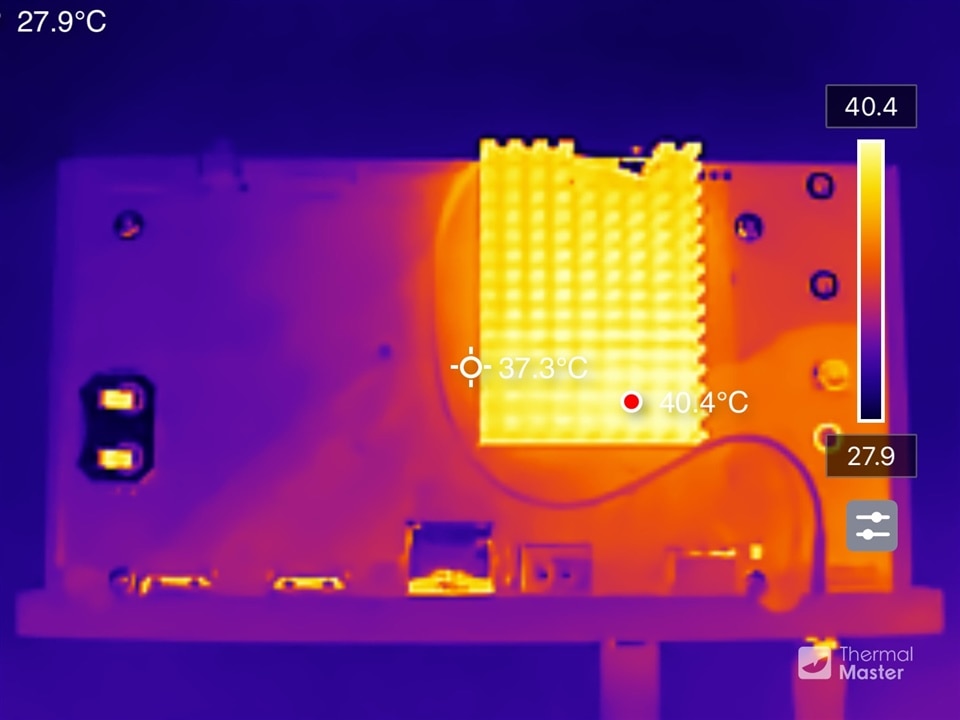
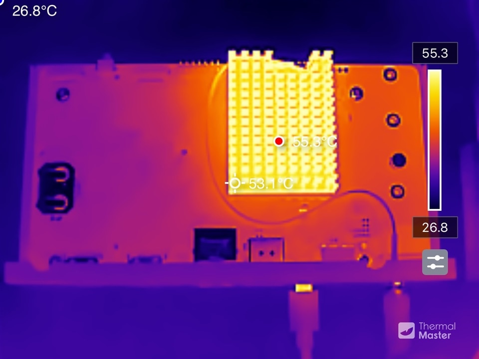
The stack is a CM5 + IO Board, an RTL-SDR dongle (Nooelec NESDR SMArt v5), a 7" HDMI touchscreen, a USB audio interface, and an optional physical control panel with two rotary encoders and four buttons wired to the 40-pin header.
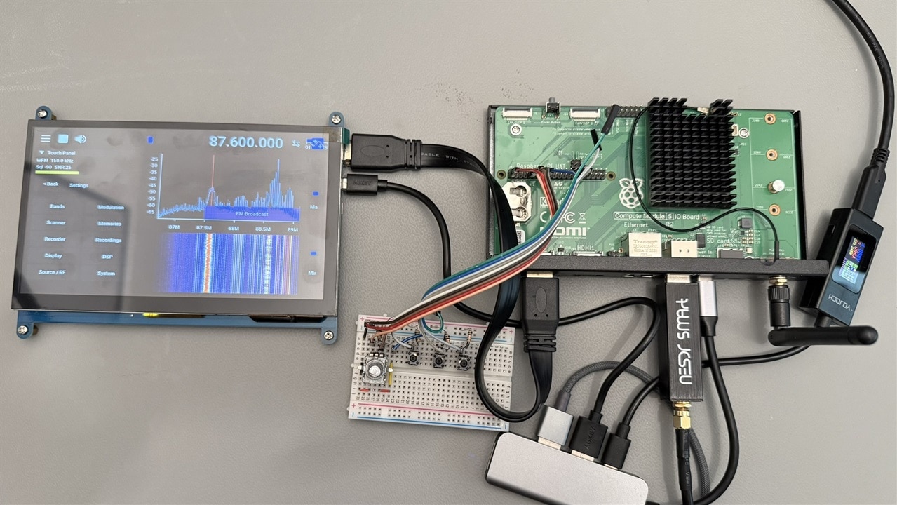
The software is a patched build of [SDR++] (https://github.com/AlexandreRouma/SDRPlusPlus) running in kiosk mode, driven either by touch or by the knobs, with both paths going through the same command interface.
Of course, you can use the standard RPi 5 for the same application, or even an older one, but I tried on an RPi 3 and this application is too heavy for that. The advantage of the CM version, as I said, is the possibility to better integrate it in a final product and the use of the embedded eMMC. The only disadvantage I noticed with the provided IO board is that, even if it's quite big, it only includes 2 stacked USB-A ports. Even plugging 2 devices (display and RTL dongle, using a different audio interface, like an I2S module), it was impossible to plug the dongle, because its thickness was blocking the second port. For this reason, a small hub was essential.
After flashing the OS (Raspberry Pi OS 64-bit) and power the board, we can connect via ssh, using the hostname and user set during the flashing:
ssh <user>@<hostname>.local
I'm not a good software developer, so I asked the help of my virtual colleague Claude (AI) to customize step by step the existing application SDR++, making the controls more suitable for a small touchscreen, instead of a desktop application, and mapping some phisical controls to the RPi GPIO.
If you want to replicate this application, you can find this version on my Github:
https://github.com/s1m0n3t/sdr-rxpro.git
So, you can proceed to install the entire environment via ssh with these simple steps:
git clone https://github.com/s1m0n3t/sdr-rxpro.git
cd sdr-rxpro
./install.sh
sudo reboot
install.sh installs dependencies, blacklists the DVB-T driver, clones and builds a patched SDR++ from source, installs the GPIO daemon as a user service, and configures the kiosk session.
Only after the reboot you can plug in the DVB-T dongle and test if it works with:
rtl_test -t
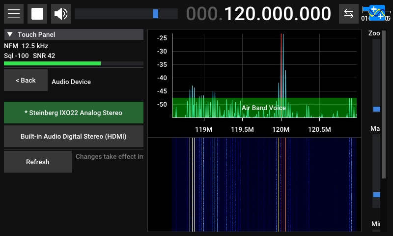
For the audio output, since it's not integrated in this CM5 + IO board, I used an USB audio adapter. After you connect one, you can select the device from Menu → System → Audio Device. The HDMI output is always present in the list, but of course you can only use it if you connect a display with integrated speakers.
Wire physical controls
I used 2 types of controls:
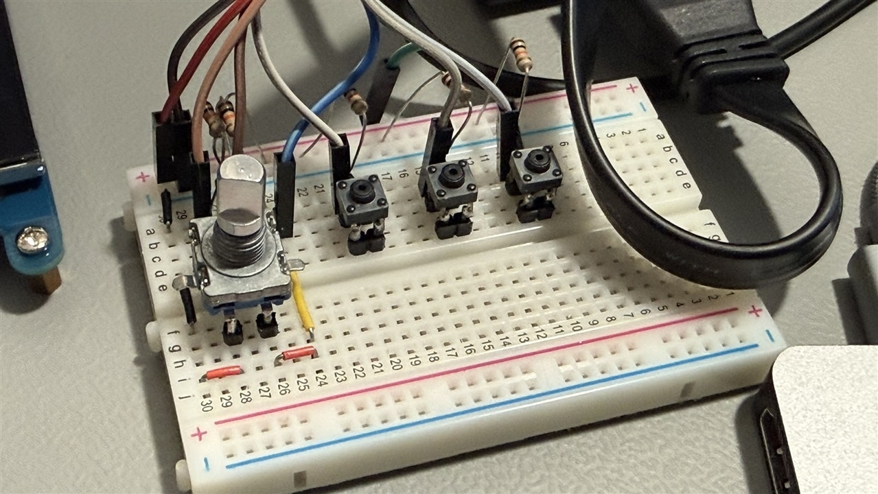
Here you can find the mapping I used:
| GPIO | Pin | Function |
| 17 | 11 | Knob 1 - Tuning - CLK |
| 27 | 13 | Knob 1 - Tuning - DT |
| 22 | 15 | Knob 1 - Tuning - SW |
| 23 | 16 | Knob 2 - Volume/Squelch - CLK |
| 24 | 18 | Knob 2 - Volume/Squelch - DT |
| 25 | 22 | Knob 2 - Volume/Squelch - SW |
| 5 | 29 | Button 1 - Mode |
| 6 | 31 | Button 2 - Band |
| 13 | 33 | Button 3 - Scan |
| 19 | 35 | Button 4 - Mute |
An additional pushbutton, already integrated in the IO board and accessible via dedicate header, is used for the soft power off and on, but the functionality was customized on the software to show a popup confirmation on the application, instead of exiting from the kiosk mode and show the OS desktop with a standard shutdown message.

Here you can see a short demo of my working setup:
Worth stating plainly, since a €25-50 dongle is being compared against instruments costing a hundred times more: an RTL-SDR's 8-bit ADC gives roughly 48 dB of dynamic range against the ~105 dB of a receiver like the Icom IC-R8600, so strong nearby signals will desense and image.
With the prototype built, the real question this RoadTest set out to answer comes back into focus: does it make sense to take this beyond a breadboard and design a custom PCB, one board carrying the CM5, the RTL-SDR front end, the touchscreen and audio interfaces, and a proper knob-and-button panel, instead of a dongle, a HAT and a handful of jumper wires?
My take is yes, cautiously. The software side has already done the hard part: starting from the open source software, the touch interface and the knobs controls customization are ready and tested. With a custom PCB, this proof of concept could become a useful tool. This receiver is versatile: VHF/UHF plus HF, touch or knobs, memories, scanning, recording, and it's customisable in the future, simply updating the software. But it is still built around a general-purpose RTL2832U/R820T dongle.
Let's consider a cost estimation for this project, before making further considerations:
Now let's compare the specs with a commercial SDR receiver:
| RTL-SDR (this build) | Icom IC-R8600 (commercial reference) | |
|---|---|---|
| Tuning range | ~24 MHz - 1.7 GHz, plus ~0.1-14.4 MHz via direct sampling (two separate windows) | 10 kHz - 3 GHz, continuous |
| ADC / dynamic range | 8-bit ADC, ~48 dB theoretical | ~105 dB spec |
| Preselection | none | tracking preselectors ahead of the mixer |
| Simultaneous bandwidth | 2.4 MHz max, one tuner | multi-MHz real-time spectrum scope |
| Digital voice decode | M17 only (via SDR++) | D-STAR, DMR, dPMR, NXDN built in |
| Independent dual receive | no - two VFOs share one 2.4 MHz window | yes |
| Price (new) | ~ €265 | ~ €2600 |
The frontend performance of the IC-R8600 are clearly on a higher level, but also the price is around 10 times higher. So, I still believe that I didn't just lose time and it could be nice to work on the next steps.
I look forward to hear different opinions from you, maybe some HAM radio expert in the community.


