RoadTest: MyIoT: Infineon Shield2Go Boards for IoT
Author: thamizharasan
Creation date:
Evaluation Type: Development Boards & Tools
Did you receive all parts the manufacturer stated would be included in the package?: True
What other parts do you consider comparable to this product?:
What were the biggest problems encountered?: Unsized Header Pins provided in the kit were useless and I had to use my personally owned Header Pins.
Detailed Review:
Unboxing Infineon Shield2Go Boards
The packing was good with individual tiny boxes, exclusively made with clear specifications of the component it contained.
Would have been extremely good if the Shield, Boot kit, Dev-MCU & Sensors are anti-static covered and put inside these tiny & big paper boxes.
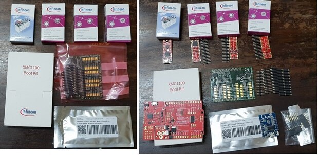
Readiness to use
All these components Shield, Boot Kit, Sensors, Dev-MCU & Sensors are bundled with the required header-pins.
Its appreciable for making us to decide on the header-pin type to use, and good to see the bundle provided with different types of header-pins.
However, its a bit of time consuming & more preparation work for us, to solder close to 100 header-pins overall in this kit.
Would have been better, if some of the components come with pre-soldered header-pins that are of standard male type.
The dual Male-Female Header-pins provided in the kit do NOT match the hole size provided on the Boot Kit board.
Infineon should consider shipping the right sized header-pins with the boards.
But then, I managed by using some personally owned male-female header-pins, to progress further.
Next, is the My IoT Adapter board that enables designers to combine the Shield2Go boards into a system. My IoT adapters act as gateways to external hardware solutions such as Arduino and Raspberry PI.
For the Infineon Shield2go adapter, I expected some clear instructions on what header-pin type to use where.
But i managed to figure them out by applying my mind. It involves using both type header-pins appropriately being the sandwiched board connecting Arduino & Shield2Go boards on both the sides respectively.
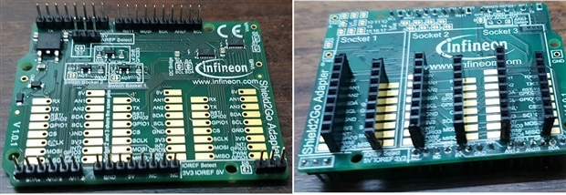
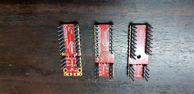
All the Shield2Go boards are following a standard form factor and a standard pin order, which makes us to blindly plug any Shield2Go board in any sequence, in the My IoT Adapter board (above pic).


The additional PINS in the Shield2Go boards designated with NC were left floating as dummy pins.
Then I soldered the male type header pins on all the 3 Sensor boards
Then I soldered the female type header pins on the XMC 2Go controller board
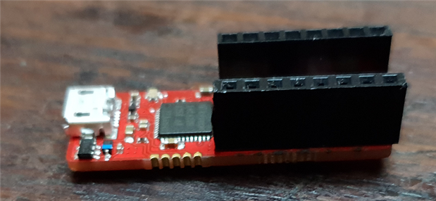
Then each sensor can be plugged in to the XMC 2Go controller board like this...
Download Dave IDE
http://www.infineon.com/dave
Also please install the J-Link driver (here illustrated version V4.74) as stated in the DAVE installation description.

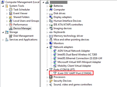
From your computer's Device Manager, note down the COM port used by the JLink CDC UART driver you just installed.
XMC 2GO with the XMC1100 Microcontroller
The XMC 2Go is programmed with XMC_2Go_Initial_Start as the factory default program. It controls the user LEDs, send predefined messages via UART and interacts with the user as it receives characters from the terminal program and sends these very same characters back to the Dave IDE terminal.
Once connected, the green LED (indicates proper power and debug) will light up.
If your XMC 2Go is powered through the USB port of your PC (with Dave IDE tool explained above), the green Power & Debug LED blinks initially at the first startup of the XMC 2Go.
After few seconds the J-Link Driver is enumerated and the green Power & Debug LED illuminates constantly.
The easiest way to power-up the XMC 2Go is via USB (Micro USB).
Once powered the 2 red User LEDs will start to blink immediately as they are controlled by the pre-programmed XMC_2Go_Initial_Start factory default program.
Download the free HTERM Terminal Program:
https://www.heise.de/download/product/hterm-53283
Set the UART with Baudrate: 115.2kbps; Data bits: 8; Stop bits: 1; Parity bit: None
Choose the COM port that you noted already from your computer's Device Manager & Click "CONNECT"
Once Connected successully, you will see some strings of data received under "Received Data" area, every 2 seconds from XMC 2GO.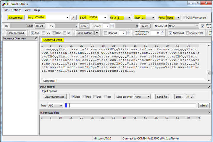
You can also interact to XMC 2GO via the HTerm terminal program.
Under "Input Control", simply type in some characters or strings in the terminal program & click "ASend". The XMC 2Go receives them and send these very same characters/strings back to the terminal program.

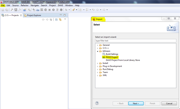
To Actually program the XMC 2Go controller, open DAVE IDE, open Tools>Import, Under "Infineon" folder, select "Dave Project"
In the next window, choose "Select Archive File", Browse to the " XMC™ 2Go Initial Start" zip file you parallelly downloaded from https://www.infineon.com/dgdl/Infineon-XMC2GO_InitialStart-GS-v01_03-EN.zip?fileId=db3a3043444ee5dc014454cda8357933
(Parent folder: https://www.infineon.com/cms/en/product/evaluation-boards/kit_xmc_2go_xmc1100_v1/ )

Expand "XMC_2Go_Initial_Start_v1.3" and click on "main.c" which is the default program loaded on XMC 2Go controller.
Initially, you can learn the programing, by editing the pre-loaded default program.
Once you get a grip of it, you can create your own programs & upload them to the XMC 2Go controller.


Once you complete the modifications. Save the project. Then, you need to Build & Compile by Clicking on "Build Active Project" icon.

Then, click on "Debug" icon & then "Run"
Finally, you check from the HTerm to confirm the re-programmed Initial_Start program.

To use Arduino IDE v1.8.5 for XMC Microcontroller (This integration will only work for Arduino IDE >=1.5 & Arduino 1.8.0 IDE might have problems with the XMC-for-Arduino releases)
Download the Infineon's XMC microcontroller library for Arduino IDE, to the Arduino's Library folder
https://github.com/Infineon/XMC-for-Arduino
Arduino > File>Preferences > "Additional Boards Manager URL", mention this:
https://github.com/Infineon/Assets/releases/download/current/package_infineon_index.json
Arduino>Tools>Boards>Board Manager>Select "Infineon's XMC Microcrontroller by Infineon Technologies AG" & click "Install" button.
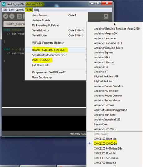
Then, Arduino>Tools>Boards>select "XMC1100 XMC2Go" board & select the COM port
You also need to download the JLink Software, for dubug probes.
Installing the Jlink software will automatically install the J-Link USB drivers and offers to update applications which use the J-Link DLL.
Multiple versions of the J-Link software can be installed on the same PC without problems; they will co-exist in different directories.
https://www.segger.com/downloads/jlink/JLink_Windows.exe
(or)
https://www.segger.com/downloads/jlink/JLink_MacOSX.pkg
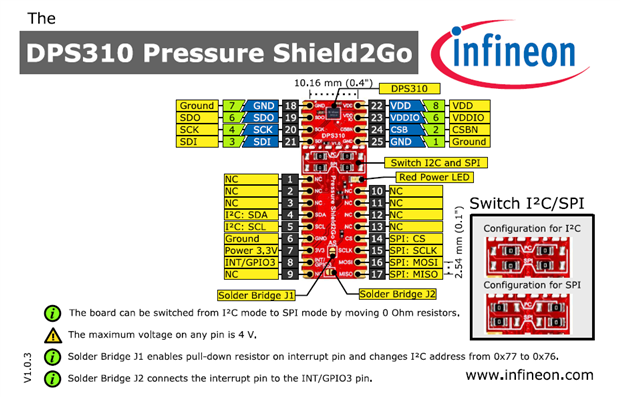
Download the Library Infineon's highly sensitive DPS310 pressure sensor for Arduino
https://github.com/Infineon/DPS310-Pressure-Sensor
Note: The DPS310 has a maximum rating of 4 V, hence do NOT connect the DPS310 Pressure Shield2Go board directly to Arduino controllers, even if the power is connected to the 3.3 V pin as the interface lines, e.g. SDA/SCL, will still be driven by 5 V. So, please use appropriate level shifting for these boards if planning to use with Arduno.
There were many Arduino codes but were giving one or other error....but finally managed to find the right code for this combination DPS310 Pressure-Sensor on XMC 2Go board using Arduino IDE.

Arduino>Serial Monitor (Infineon DPS310 Shield2Go Pressure sensor)
The readings are instantaneously accurate & quick (very precise), readings were captured every 2 seconds once (as mentioned in the program code).

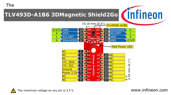
Infineon 3D Sense Shield2Go
Download the Library 3DSensor Shield2GO board based on the XMC 2Go evaluation board
https://github.com/Infineon/TLV493D-A1B6-3DMagnetic-Sensor
Note: The TLV493D has a maximum rating of 3.3V, hence do NOT connect the TLV493D 3D magnetic sensor Shield2Go board directly to Arduino controllers.
Even if the power is connected to the 3.3 V pin as the interface lines, e.g. SDA/SCL, will still be driven by 5 V. So, please use appropriate level shifting for these boards if planning to use with Arduno.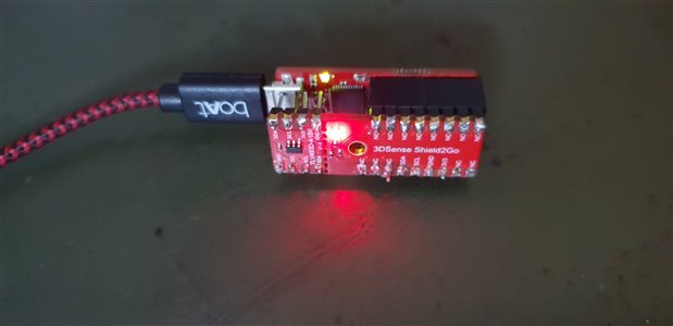
For rhe 3DSense Shield2Go on XMC 2Go board using Arduino IDE, use the following code:
https://github.com/Infineon/TLE493D-3DMagnetic-Sensor

Arduino>Serial Monitor (Infineon 3DSense Shield2Go sensor)
The x,y,z readings are instantaneously accurate & quick (very precise) & the update rate is set to 3 (fastest is 0 and slowest is 7
Infineon TLI4970 CurrentSensor Shield2Go (This is a high-precision current sensor based on Infineon´s proven Hall technology)
TLI4970 is an easy-to-use, fully digital solution that does not require external calibration or additional parts such as A/D converters, 0 pAmps or reference voltage.
* AC & DC measurement range up to ±50A
* Highly accurate over temperature range and lifetime (max. 1.0% (0 h),
* 1.6% (over lifetime) of indicated value)
* Low offset error (max. 25mA)
* High magnetic stray field suppression
* Fast overcurrent detection with configurable threshold
* Galvanic isolation up to 2.5kV max. rated isolation voltage (UL1577)
* 16 bit digital SPI output (13 bit current value)
* Small 7 mm x 7 mm SMD package
## Target Applications
* Photovoltaic and general purpose inverters
* Power supplies (SMPS)
* Battery chargers
* Lighting applications
* Electrical drives
Download the Library for CurrentSensor Shield2GO on XMC 2Go controller for Arduino

https://github.com/Infineon/TLI4970-D050T4-Current-Sensor
First upload the "configEEPROM" code
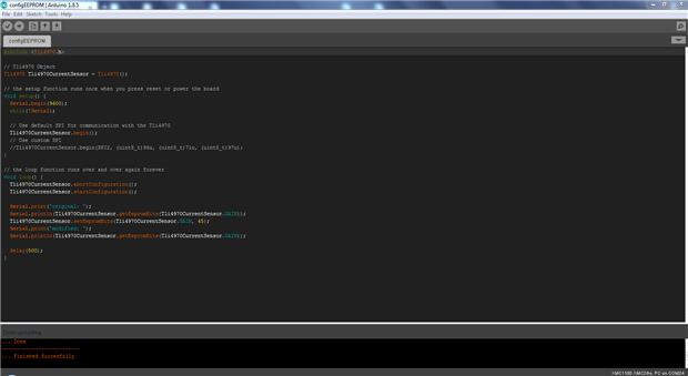
Arduino>Serial Monitor (Infineon CurrentSensor Shield2Go)
Then upload the "getCurrent" code

Arduino>Serial Monitor (Infineon CurrentSensor Shield2Go)

Infineon XMC 1100 Boot Kit
Infineon XMC 1100 Boot Kit is compatible with Arduino shields and you can stack it in-between other shields as well.
Boot Modes available
– UART Bootstrap
- Loader Mode
– User Mode (Halt After Reset)
– User Mode (Debug), is the Default Mode
– User Mode (Productive)
The Boot modes can be configured using:
DAVE IDE https://infineoncommunity.com/dave-download_ID645 (or)
MemTool https://www.infineon.com/dgdlc/en?dcId=8a8181663431cb50013431cb500b0000&downloadTitle=Infineon-MemTool-DT-v04_71-EN.zip&…
If using DAVE IDE, then you need to install the DAVE Apps Library Manager from the Help Menu.
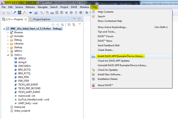
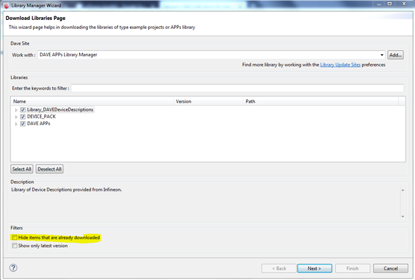
Select the following libraries (remember to uncheck the Filters to get the list)
Library_DAVEDevceDescriptions, DEVICE_PACK, DACE APPs

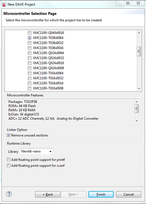
Open DAVE, new PROJECT "Roadtest_Blinky" & select the XMC1100 boot controller
Next, lets create a New App for Clock (to make an embedded LED blink at a frequency & timing)
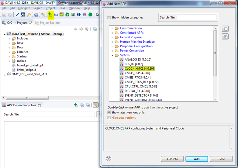
Open the newly created App "Clock_XMC1_0" (double-click on the block)

Under "General Settings" set the Main Clock frequency to 8Mhz. and Save it.

Next, lets create another new App for the Digital IO port (to define the port for one of the embedded LED03)

Now, lets create a Port & define the Port No (P0.5)
Next lets create one more App for the Timer (to make the embedded LED03 at port P0.5 blink at a rate)

And define the embedded LED03's blink interval as 0.1s (100000 us)

Finally, Click "Generate Code", "Build Project", "Download Code", "Debug Perspective", "Run Code"
Outcome: The embedded LED03 (port P0.5) will blink at 8Mhz at 0.2s interval.


Wemos ESP8266 (Wi-Fi module/Dev board)
Download and Install the Wemos ESP8266 driver for Windows / Mac.
https://wiki.wemos.cc/_media/file:ch341ser_win.zip (or)
https://wiki.wemos.cc/_media/ch341ser_mac-1.4.zip
Open Arduino IDE > Preferences:
Under "Additional Boards Manager URLs:", paste the following URL
http://arduino.esp8266.com/stable/package_esp8266com_index.json

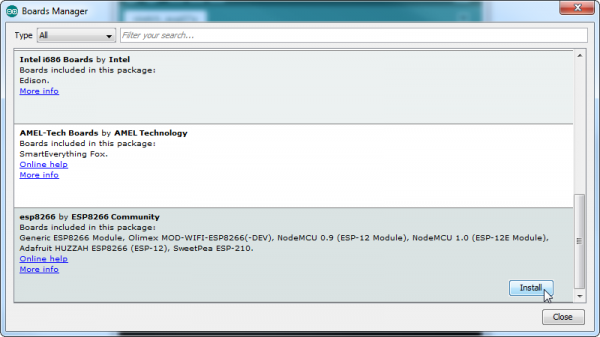
Under Arduino>Tools>Boards>Boards Manager, select the "ESP8266 by ESP8266 Community" and click on "Install"
Under Arduino>Tools>Boards, select "Generic ESP8266 Modules"

I just created a simple project that would:
Tested by accessing the Wemos IP address from my Mobile Phone (which was connected to the same WiFi network, obviously with some other IP) and I turned the Switch (pin2 in my example, which is D4 at Wemos) to ON


Additional Reference:
Difference between Arduino and WeMos D1R2/Mini PIN Assignments...

I also read some of the recent articles about Infineon that gave me more insights & motivation...
1. "Electronics Maker" magazine (Sep-2018) - page26 -> Infineon listed as one of the 15 most promising Semiconductor Companies
2. "Electronics Maker" magazine (Sep-2018) - page29 -> Infineon's Barometric Pressure Sensor DPS310 for Consumer Applications
3. "Electronics Maker" magazine (Sep-2018) - page42 -> Infineon's XMC4100, XMC1300 with MATH co-processor, a benchmark write-up by Pablo (who worked with Infineon as Application Engineer for 8bits/16bits/XMC microcontrollers, now as Application Engineering Manager @ Infineon, El Segundo office in California), responsibilities on MOSFETs, Gate Drivers and Controllers for low voltage applications.
Feeling great to roadtest Infineon's Shield2Go products, which are amazing to prototype different projects for different applications.
Overall, a lengthy roadtest, but worth it for the experience gained.
Next, personally, I will be exploring Infineon's XMC 4100 family that are with high resolution PWM modules for Industry grade applications requiring high switching frequencies with NO compromise on processing capacity.


Top Comments
I am having the same issue. The holes are too small it seems. I even hurt myself and got a cut…
Hi both, all,
In order to avoid confusion - the solderless Pin headers that are part of the package are meant for the My IoT Adapter and not for the XMC bootkit.
Have fun and enjoy the Shields!
Cheers