RoadTest: Avnet Ultra96 Dev Board
Author: dimiterk
Creation date:
Evaluation Type: Semiconductors
Did you receive all parts the manufacturer stated would be included in the package?: True
What other parts do you consider comparable to this product?: There aren't many Ultra+ ZYNQ devices in this price point category.
What were the biggest problems encountered?: 1. JTAG switch was messed up during assembly. 2. 40 pin count connector was set to 1.8V so interfacing with 3.3V devices is not possible without the use of voltage translators. 3. You definitely needs a beefed up system with a lot of RAM , SSD hard-drive and at least a core I7 to avoid waiting for hours when compiling a design with Vivado.
Detailed Review:
Introduction
The Ultra96 board features a ZYNQ Ultrascale which comes with plenty of peripherals such as WIFI/BLE, SD card, Display port, USB3 and USB2 downstream ports. The board also features a 40 pin connector connected to Bank 13 which is set to 1.8V and
a high speed FPC connector that comes with two MIPI-CSI interfaces. These are mostly used for interfacing with cameras.
Initial snag.
My initial idea was to build a AI vision based project with the Ultra96 board. The project hit a snag when while unpacking the board I noticed the JTAG switch was kind of smashed at a weird angle.
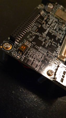
Anyway , I tried to boot up the board and lo and behold nothing happened. After careful inspection I see that the traces near the switch were lifted.
The switch is connected to the bootstrap pins which define the boto method. If the pins are floating the SOC essentially does not boot up.
I ended up fixing it by soldering two resistors to the pins to the GND pin of the fan. This happens to be slightly dangerous since the pin adjacent to the GND pin the 12 V for the fan.Seems kind of weird that this got past QA.
Project Description
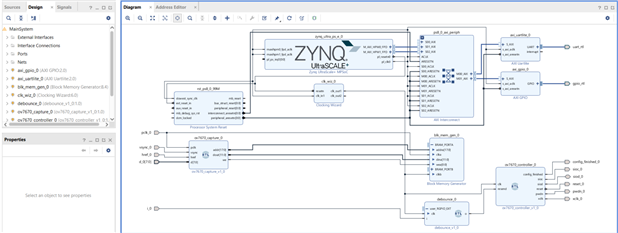
The initial was to implement an AI algorithm in the PL. The architecture of the program is as follows.
An OV7670 VGA camera is used to get the images into the fabric. The OV7670 module uses an slave AXI stream interface which pipes the data directly to the AI core.
In addition an AXI stream to VDMA core can be used to get the data to the DDRL3 side of PS section allowing one of the ARM52 cores to serve the image over IP.
Vivado 2018.2 does not have any AI IP cores so one has to design this from scratch. Since this is a big undertaking the project was revised to just send the data to the PS section and run the AI on the PS.
I received a Ultra96 board. My idea was to build a vision processing pipeline to be used with an external camera sensor.
This development board comes with a ZYNQ Ultrascale.
The UktraScale chips are a category apart compared to the common ZYNQ SoC.
.

The Ultra96 uses a xczu3egsbva484 chip. This comes with four ARM-A53 cores and two deterministic ARM-R5 cores as well as MALI GPU.
The design I had in mind however would only leverage the PL (Programmable logic section) as well as using one of the cores for a Linux based OS.
By default the operating system used on Ultra96 is PetaLinux. The workflow for this particular distribution is involved so I ended up using PYNQ 2.1.
The main problem I encountered is that compilation is very very slow. So the project architecture was revised a bit in order to make this more doable.
The idea is to implement the image capture IP for the camera in the PL and use and external PYNQ overlay to do the image recognition. in the end I only ended up testing the camera.
Luckily it can interface with the 1.8V bus since the camera pin are compatible from 1.8 to 3.0V.
I built a small test setup with a number of standard peripheral such as GPIO, I2C , SPI and UART.
Once the bitstream is exported one has to open the SDK and write the main app. I verified this with a simple blink app.

The next step was to get the PYNQ working. PYNQ allows high level programming using Python with custom overlays.
Following this in steps:
1.
Plug in a USB cable , open a browser and log in. I found that Firefox would not work as expected while Edge (Microsoft ) did not give me any issues. YMLV.
Open a browser and enter 192.168.3.1. The use the password xilinx to log in.
2.
Run the Jupyter file that sets up the network.
3.
Edit the network file by issuing the following:
Sub network name with you WIFI network.
sudo nano /etc/resolv.conf
nameserver 8.8.8.8
search "Network name"
4.
sudo apt-get update
sudo apt-get upgrade
5.
make permanenet
/etc/resolvconf/resolv.conf.d/head
6.
Install
sudo pip3 install git+https://github.com/Xilinx/BNN-PYNQ.git
python3 setup.py install
My second program was interfacing an ov7670 camera with the Ultra96. The OV7670 needs a 3.3V power input
so I had to generate a 3.3V from a 5V output. The block diagram is as follows.
At the moment I still have to tweak the camera settings and revise the VDMA app instead of sending data via UART.
The plan is to use the camera frames and PYNQ to implement a CNN.
The board did not come with a MiniDisplay to VGA converter so I had to borrow one. Anyway this is what I managed to get until now.

PS: It takes 70 minutes for a full compile on a core i5 laptop.


