RoadTest: Digilent Zybo Z7 + Pcam 5C
Author: gecoz
Creation date:
Evaluation Type: Development Boards & Tools
Did you receive all parts the manufacturer stated would be included in the package?: True
What other parts do you consider comparable to this product?:
What were the biggest problems encountered?: The Zybo Z7-10 FPGA fabric is too small to be usable for video processing application involving machine learning. The recommended minimum board for such applications is the Z7-20.
Detailed Review:
After I had a chance to review the Digilent Arty-S7 board last year, which introduced me to the Xilinx Spartan-7 FPGA family, when I saw the new Zybo Z7 up for review, I had to apply to give the Zynq architecture a try.
The main motivation behind my application was to test how good the Zynq architecture would perform when applied to machine learning. In particular, since the kit under review included also the Pcam 5C, the platform would be an ideal candidate for a face recognition application, which could leverage both the ARM cores and the FPGA fabric.
Before applying, I had a look at the tools and libraries available from Xilinx and Digilent, supporting both the board and the machine learning algorithms needed, and found many interesting projects, which made me feel confident on the feasibility of the project.
To be honest, going through the board documentation, I did find something suspicious on the Zybo-Z7 migration guide:
...
reVISION SDSoC Platform
SDSoC and the reVISION libraries make it possible to do FPGA accelerated video processing using openCV functions in an all C/C++ development environment. Digilent will be enabling this design flow on the Zybo Z7-20 by providing a reVISION capable SDSoC platform for it in the future. Those using the ZYBO for video processing (or that are interested in doing so) should consider if migrating a project into SDSoC will enable improvements. For more information on reVISION, see Xilinx's reVISION Zone.
Those interested in using reVISION should migrate to the Zybo Z7-20. The Zybo Z7-10 does not have enough programmable logic resources to properly implement a reVISION platform.
Larger FPGA Option
If you would benefit from having more FPGA resources, you have the option to migrate to the Zybo Z7-20, which includes a much larger ZC7020 Zynq part. The process of migrating to the Zybo Z7-20 is no more difficult than migrating to the Zybo Z7-10, which has the same ZC7010 Zynq part as the ZYBO.
Basic video processing applications designed on the ZYBO or Zybo Z7-10 will often use most of the available resources in the programmable logic. For this reason the Zybo Z7-20 is recommended for those interested in video processing.
...
I chose to downplay those warnings: after all the roadtest was clearly inviting applications that would involve video processing of some sort (hence the inclusion of the PCAM 5C), and push the Z7-10 board capability to its limits, so I thought those warnings perhaps were just another marketing up-selling technique. Only after quite a lot of struggle I came to realise they were not! But more about this later.
Before getting into the body of my review, I would like to thank rscasny for letting me stretch the roadtest deadline, in order to complete the review (and enjoy my holidays!).
For this roadtest, the kit includes the Digilent Zybo Z7-10 board and Digilent Pcam 5C camera. Both arrived in the Element14 box, nicely protected by pink bubble wrap, each enclosed by the very distinctive Digilent packaging. The Zybo board comes nicely padded in layers of pink foam. The is really very little to add about the packaging, so let's explore each item in more detail, to understand what they have to offer.


This Digilent development board is the upgrade of the ZYBO board. Just like its predecessor, it features a Zynq device (the Z7-10 employs a XC7Z010-1CLG400C) at its core. The Zynq architecture offers a great amount of flexibility, due to the availability of both a dual ARM Cortex-A9 based (@ 667 MHZ) processing system (PS) and the Artix (Z-7010) based FPGA programmable logic (PL).
To match this powerful device, the board provides the following memory: 1 GB DDR3L RAM (with 32-bit bus @1066 MHz), 16 MB Quad SPI Flash and a microSD slot. It also offers plenty of connectivity, via the Gigabit Ethernet, the USB-UART bridge, the USB-JTAG circuitry and the USB 2.0 OTG (On-The-Go). Audio processing is supported thanks to the many connectors available on the Zybo Z7 (line in, microphone and headphones jacks) and the onboard SSM2603 audio codec. Similarly, for the video, there are HDMI input, HDMI output and a MIPI CSI-2 camera port.
As for “wired” GPIO, there are 4 LEDs (green), 1 RGB LED, 4 switches and 6 push buttons, so plenty to play with. And if you need more I/O, the system can be expanded using the 5 Pmod ports available.
The board provides a few jumpers, which can be used to select the power source and the boot mode. For the power, the user can choose between using the USB, or providing an external 5V power source (connected via the power jack or the jumper pins). I ended up using the external power, as I have experienced some issues using the USB connector, due to the limited amount of current available from the laptop USB port, which caused the Zybo to hang randomly.
The board can boot from the microSD card, from the onboard QSPI flash memory or via JTAG. The QSPI flash memory comes preloaded with the OOB demo.
More details on the Zybo Z7 can be found on the Digilent website.

Together with the Zybo, the roadtest included the Digilent Pcam 5C camera. This camera can be connected to the board using the MIPI CSI-2 interface. This serial interface is the standard for attachment of cameras to processors, and it is the same that is used on Raspberry Pi boards. The Pcam 5C has 2 lanes for data (one-way connection), allowing for high speed data transfer from the camera to the board (each lane can support speed up to 1 Gbps). The physical hardware layer interface implements the D-PHY specification, a low-power, high-speed, very scalable specification, which supports any number of data lanes (I’m mentioning those details, as they will be extremely useful when implementing the interface on FPGA).
As for the specification of the camera, the Pcam 5C uses the OV5640 color CMOS image sensor. Such sensor has a 5MP resolution and supports the following video modes: QSXGA@15Hz, 1080p@30Hz, 720p@60Hz, VGA@90Hz and QVGA@120Hz, although Digilent support is only limited to the tested 1080p and 720p modes.
On the camera board there is also a 7-pin header (on the picture on the left, the header is partially covered by the crocodile clip used to hold the board) for access to auxiliary camera signals (like 2 GPIO, auto-focus control signal). The camera comes fitted with M12 lens.
The full specification and extra resources for the Pcam 5C can be found on the Digilenti website.

After introducing the kit, the question is: what can we do with it? As mentioned before, the Zybo Z7-10 employs a Xilinx Zynq architecture, which offers a great amount of flexibility, due to the availability of both a dual ARM Cortex-A9 based processing system (PS) and the Artix (Z-7010) based FPGA programmable logic (PL).
This means the board can be used in any of the following configurations:

Although dependent on which configuration is chosen for the system, the application development workflow for the Zynq can be generalised in the following steps:
To handle the complexity of the tasks, Xilinx offers the following set of development tools, which help with one or more steps of the workflow:
Going into details for each of the above tools is beyond the scope of this review, as each would deserve a book (or more) of its own! If you are interested in learning more, I would urge you to refer to the vast Xilinx bibliography on the subject, but be prepared, the amount of information is huge! Also, Internet and the search engine are you friends: just type the name of the tools and you will be greeted with tens of links, covering just about all the aspects you might be interested in.
Just one remark: the tools are quite powerful, but they are very resource-hungry! You need a decently computer in order to be able to work at a reasonable pace, with plenty of RAM and disk space. I personally use a 16GB machine, with 500GB SSD disk. Also, during the development, you need to make sure you have always plenty of disk space available, as the build by-products can easily eat away many GB (especially if you work on many versions of the tools, many variations of a project and/or decide to go down the Petalinux route).

Demos
The Digilent website contains an ample set of resources, including a few demos to be used with the board. In general, the information provided is sufficient to successfully implement the demo, but the only problem is that each demo has been developed using a different version of Vivado, which can cause an headache if you decide to try them all!
Although I have implemented the Video Workshop demo (shown in the picture on the right), I will not include the details in this roadtest, as I think my fellow roadtesters have already made an excellent job in describing them in very fine details, so I would rather point you to read their reviews if you are interested. The rest of the review will instead focus on the project implemented on the Zybo Z7-10.
The idea behind the application for this roadtest was to leverage the Pcam 5C and the Zybo board to build an AI based access control gate. The gate would grant access using face recognition: the person willing to pass across the gate will have to stop in front of the camera, stand still while the recognition algorithm works its magic, and then, if the face is recognised, access will be granted.
To try and match the application to the limited resources available on the Zybo Z7-10, some assumptions will be needed. In particular, the gate will be restricted to allow only one person at time through (a bit like the automated custom passport control checkpoint you find at airports nowadays). This way the neural network can focus on detecting and processing only 1 face per frame, reducing the time required by the computations.
Also, the person will have to stand in front of the camera till their image has been successfully captured and processed. As the time required for face recognition will be in the range of few seconds, this imply the person will have to stand for few seconds. The idea is to use the FPGA fabric to implement hardware acceleration for the neural network processing, thus aiming to achieve performance that would not exceed 5 seconds/person recognition (this figure has been chosen only on basis of a reasonable time response for the system, in order to be of any practical use in real applications).
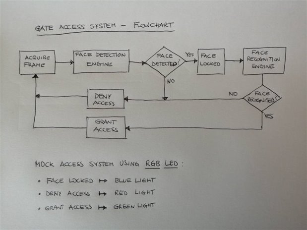
The access control side of the system will be mocked using the RGB LED available on the board. Each state will have a different colour assigned: blue for face detected, red for denied access and green for granted access.
From a functional point of view, the gate access system can be represented by the following functional blocks:
The picture on the right illustrates how the flow is organised. For sake of simplicity, the gate control block is mocked using the RGB LED available on the board.
From a system development point of view, following the workflow described earlier, we can identify the following steps:
Lets explore them, one by one.
To be able to define what hardware is needed to implement the system, let’s go through our requirements again: the system needs to be able to capture video from the Pcam 5C (input) and make the stream available for processing. For the output, the only must is to be able to drive the RGB LED, although having also a display available via HDMI is a nice to have. For the processing of the image, I’m going to use machine learning algorithms, which can be accelerated in hardware. Xilinx has been very active on the machine learning front, providing many tools and libraries which contain hardware accelerated cores, that can be used “out-of-the-box”.
As starting point for hardware implementation, Digilent has made available several reference model for their boards on GitHub. There are a few repositories for the Zybo Z7-10, but none of them offer support for the Pcam 5C. There is a workshop example platform, which targets the Zybo Z7-10 and the Pcam 5C, which can be used as a starting point. Also, to gain more insight on what IPs are needed to create a working video pipeline, and also to extend the system to include the GPIOs (LEDs, switches, etc), it is useful to take a look at how it is implemented for the Zybo Z7-20 (which include Pcam 5C support).
The picture below shows the high level design for the hardware platform (the control signals are not shown).
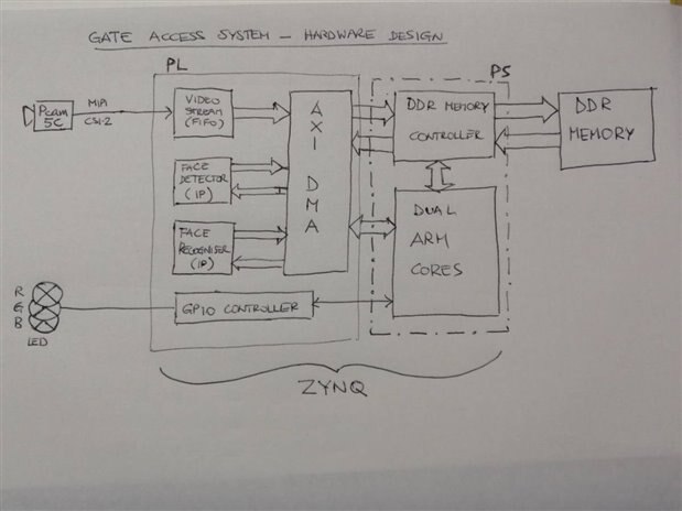
Lets explain what the blocks do, starting from the video processing. The VIDEO STREAM block implements the MIPI CSI-2 receiver interface, decodes the data and produces a FIFO data stream. The data stream is stored on the board DDR memory thanks to the AXI DMA (Direct-Memory-Access) block.
This is necessary, as the system will not process real time video stream, but only single frames extracted at specific time.
The processor will initiate the face detection stage and orchestrate the data transfer to the FACE DETECTOR custom IP block. Again, DMA is used to transfer data across. Similarly, if the FACE DETECTOR will signal a positive detection, the FACE RECOGNISER will fetch the frame data to process the recognition using DMA. Finally, the GPIO controller (which will also implement a PWM module), controlled by the processor, drives the RGB LED on the board.
All the blocks are available on Vivado as free IPs, except the 2 custom IP that deal with face detection and recognition, which will need to be implemented. For face detection, I have found a nice implementation, which can be used with Vivado HLS to create the IP from C code. The code can be found here.
I have downloaded the code, set up the project, run the simulation and, finally, run the synthesis, below you can see the result.

Well, the output picture, obtained running the simulation, shows that the algorithm works pretty well, but the resource utilisation report is bearer of very bad news! Looking at the various resources, this project overrun the FPGA resources available with the Zynq XC7Z010, so the freshly synthesised IP will not fit into the fabric!! And this IP would only take care of face detection, I would still need room on the FPGA for the face recognition IP, not to mention the space needed to synthesise the hardware platform (which, even with trimming all the IPs and I/O not needed from the Digilent reference implementation, still accounts for about 58% of the available fabric space). I have also looked at other implementations of the face detector (based on Viola-Jones algorithm), but even the most "lightweight" found would still use too many resources. This throws a huge spanner into the workings of this implementation: hardware acceleration is simply not feasible on this Zynq device, as the fabric is too small. This has been a huge oversight on my side, I should have paid more attention to the warnings on the documentation and do a bit more investigation on the matter before starting full steam the implementation. That would have saved me a huge amount of time... well, you live and learn!
Not all is lost: in my planning for the roadtest I did account for this eventuality, and I have a plan B: bypass the hardware acceleration altogether and implement all in software, but this implies that the timing requirement will likely not be met! Although disappointing, I thought it is still a valid exercise to carry on completing the project.
To make things easier, and to try and leverage as many libraries as possible, the next hardware platform must be able to run a Linux distribution. Again, Digilent offer some reference hardware implementation for Petalinux, but the problem is that the one for the Zybo Z7-10 does not include support for the Pcam 5C.
Fortunately, the one for the Zybo Z7-20 does include the Pcam 5C support, and can be adapted to run on the Z7-10. The necessary changes can be found on this post on the Digilent forum (by the way, the forum is a great place to find lots of useful information). One remark: the design will encompass the use of DIV2RGB IP block, which comes with debug enabled by default. This cause the generation of the logic analyzer (ILA) module, which utilise quite some space in the FPGA fabric, therefore, before going on with the synthesis, disable the debug option. A second remark is regarding the MIPI CSI-2 RX receiver IP: this is a "paid for" IP, and in order to use it you need a licence. Fortunately, thanks to Fred27 that kindly donated his SDSoC licence to me, I got it covered. The alternative to using the paid for IP is to grab the platform HDF file generated by Digilent themselves, which is available as attachment in the post referenced above. Another, more complex and time-consuming alternative is to use the Digilent own free IP cores, available on the Digilent Vivado library, which are slightly different, thus requiring a bit of rework on the video pipeline (those IPs are used in the Zybo Z7 video workshop).
The pictures below show the hardware design in Vivado.
| {gallery} Vivado HW design |
|---|
Vivado Hardware Design |
Hardware diagram |
To complete the hardware platform creation, just go through the usual workflow: Synthesis, Implementation and Bitstream Generation. Once completed, we need to export the hardware (HDF platform file), so can be later used to include the support for the new hardware into our Linux OS, which is the next step.
The next step is to create the OS layer. Such layer will contain the kernel and the drivers to control the hardware components, and will be based on Petalinux.
Petalinux is another Linux distribution, created ad-hoc by Xilinx to support their hardware. It is based on Yocto, the standard build system used to create Linux distribution, which enormously simplifies the creation process.
On the Digilent GitHub there are many Petalinux distributions available. We need to use the one that matches the hardware we just created in Vivado. Once again, this distribution is intended for the Zybo Z7-20, so we need to tweak it to adapt it for the Z7-10 (again, the post on the Digilent forum, referenced before, helps explaining the necessary changes).
Basically, creating a distribution implies creating a kernel image, a boot image, including the device tree and finally creating a root file system. All those parts are configurable, and the Petalinux build allows that by using the familiar package configuration wizard. The whole process is pretty streamlined, and if you don't deviate from the standard build, it is pretty straightforward. At first, if you take a look at the build tree and the configuration files, trying to change some configuration, or add some new application (which, by the way, can be even added from source files, with the cross-platform build system taking care of producing the right executable for the right architecture for you) can be daunting.
But, as always, spending a bit of time playing with it and reading the Xilinx Petalinux guide (I'm not including a link, because each Petalinux version has its own user guide), you can quickly grasp the basics.
Back to the project, I’m only interested in generating the boot image, the device tree and the kernel image, as I am replacing the Petalinux with Debian Buster distribution (which is done by replacing the root file system).The information about the device tree are automatically extracted from the hardware description file created with Vivado when exporting the hardware.
Before launching the build of the Petalinux distribution, another change needed is to switch from in memory to SD card boot. Again, all the information to successfully configure and build Petalinux are available from Digilent, on the Readme file of the GitHub repository, and there is also information on how to prepare the SD card and copy the distribution onto it. The build process will take some time and, depending on how you have configured your build, will us up quite a few GB on your disk.
As said, I am not using the Petalinux root file system, but I am creating a Debian Buster based root file system. This link explain pretty well how to "bootstrap" a root file system for armhf architecture (which is our ARM Cortex-A9) from a host platform. The only changes needed are relative to the Debian distribution used (I am using buster and the respective repositories) and the specific information about the system (like the hostname, partitions, etc...).
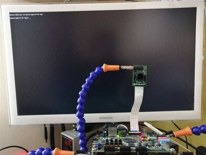
Once the basic root file system has been created, and copied onto the SD card, such card can be used to boot the Zybo (make sure you set the jumper JP5 on the board on the correct position). This standard build should allow the use of the the Ethernet and the HDMI output port on the Zybo, which means the board can be connected to a monitor and to the Internet (which is a requirement, in order to be able to configure the system according to the need of the Gateway Access application.
On the right, you can see the picture of the Debian Buster login console on the Zybo.
Once the OS layer has been prepared, we can now focus on the actual application: gate access control using deep learning. I have already introduced the flowchart, illustrating the basic logic of the application. Basically, the core of the functionality is based around machine learning. The algorithms use OpenCV (face detection) and Tensorflow (face recognition) . The video device is controlled using the v4l2 library., while the RGB LED is controlled using UIO driver (I wrote a Python version of Digilent's libuio and libpwm). To speed up the development, I have implemented the solution using Python 2.7. The choices of the versions for the software packages have been mostly forced by the availability on the Buster repository, as I wanted to avoid having to build the packages from source. Unfortunately, some version combination just weren't working, with particular regard for Tensorflow. This has forced me to build it from source. If you don't know Tensorflow, it is a software used to support the kind of calculation (tensor algebra) used by neural networks. It has been developed as an internal tool by Google, and then release to the public later on. Its java based build system, Bazel, it is a very convoluted piece of software, and I had to build this from source too. To speed up the builds, I tried to set up a cross build system, so I could leverage the power of my laptop. Unfortunately, I kept getting errors while building, so I had to resort to native build on the Zynq. While Bazel build went pretty smooth, and lasted only few hours, Tensorflow's took solid 4 days to complete on the Zybo Z7-10 (and I had to repeat the build a few times, to find the right configuration settings for the build!).
The application is pretty simple: it is basically an indefinite loop, where in each loop the a frame is captured from the camera. By default, the gate is in "deny access" state. The frame is processed, looking for a face. If the face is detected, the state change to "face locked", and the face part is extracted from the frame, and passed to the face recognition engine for processing. The recognition engine is actually a classification network, which will try and label the face. If the label matches any of the names in the allowed list, the access is granted, and the RGB LED turns green for 5 seconds, otherwise it turns RED. Both the labels and the allowed persons list files can be found in my Github repository.
The details of the machine learning workflow, used for this application, can be found in the appendix. Below, I include the Python source file, used for the application.
| {tabbedtable} Tab Label | Tab Content |
|---|---|
inference_tflite_facecascade.py | import tensorflow as tf import cv2 from keras.models import load_model import numpy as np
import json import select import v4l2capture import time
from pwm_rgb import PWM_RGB,BLUE,GREEN,RED
pwm=PWM_RGB(4,0) pwm.setPeriod(60000) pwm.red() pwm.enable()
modelfile='./model_full_face_recognition.h5'
allowed = None
with open("allowed.json", "r") as read_file: allowed = json.load(read_file)
try: import cPickle as pickle except ImportError: # python 3.x import pickle
with open('labels.p', 'rb') as fp: label_map = pickle.load(fp)
# Load TFLite model and allocate tensors. interpreter = tf.lite.Interpreter(model_path="converted_model.tflite") interpreter.allocate_tensors()
# Get input and output tensors. input_details = interpreter.get_input_details() output_details = interpreter.get_output_details()
# Open the video device. video = v4l2capture.Video_device("/dev/video0") size_x, size_y = video.set_format(1920, 1080) video.create_buffers(1) video.queue_all_buffers()
# Start the device. video.start() time.sleep(10)
while True: # Wait for the device to fill the buffer. select.select((video,), (), ()) image_data = video.read_and_queue() frame_mat = np.reshape(np.frombuffer(image_data, dtype=np.uint8),(size_y,size_x,3),order='C') frame_mat=cv2.flip(frame_mat, 0)
faceCascade = cv2.CascadeClassifier('haarcascade_frontalface_alt2.xml') gray_mat = cv2.cvtColor(frame_mat, cv2.COLOR_BGR2GRAY) start_time=time.time() faces = faceCascade.detectMultiScale( gray_mat, scaleFactor=1.1, minNeighbors=5, minSize=(50, 50), flags=cv2.CASCADE_SCALE_IMAGE ) print("Detection run time: %s s" % (time.time()-start_time)) if len(faces)==0: print("no faces detected") pwm.red() continue
pwm.blue()
(x,y,w,h)=faces[0] frame_mat = frame_mat[y:y + h, x:x + w] frame_mat=cv2.resize(frame_mat,(150,150)) frame_mat=np.reshape(frame_mat,[1,150,150,3])
input_data = frame_mat.astype('float32')
interpreter.set_tensor(input_details[0]['index'], input_data)
try: start_time=time.time() interpreter.invoke() print("Recognition run time: %s s" % (time.time()-start_time)) except: raise Exception("invoke failed!")
output_data = interpreter.get_tensor(output_details[0]['index']) id = [key for (key, value) in label_map.items() if value == np.argmax(output_data)][0] if id in allowed.keys(): pwm.green() print("User \033[1;32m%s : ACCESS GRANTED!\033[0;30m" % allowed[id]) else: pwm.red() print("User \033[1;31munrecognized : ACCESS DENIED!\033[0;30m")
time.sleep(5)
video.close() |
| uio.py | import os import mmap
class UIO(object): def __init__(self, uioNum,mapNum): if (uioNum < 0) or (mapNum < 0): raise Exception("Invalid UIO device or map number. Check /sys/class/uio for more information about the available UIO devices") self.uioNum=uioNum self.mapNum=mapNum filename = '/sys/class/uio/uio%d/maps/map%d/size' % (uioNum, mapNum) uiofile= '/dev/uio%d' % uioNum if os.path.isfile(filename) == False: raise Exception("UIO device or map number not found. Check /sys/class/uio for more information about the available UIO devices") fileObj = open(filename) self.mapSize = int(fileObj.readline(),0) fileObj.close() try: self.uio_fd = os.open(uiofile, os.O_RDWR) self.mmap = mmap.mmap(self.uio_fd,self.mapSize, mmap.MAP_SHARED,mmap.PROT_READ | mmap.PROT_WRITE, os.sysconf("SC_PAGE_SIZE")*self.mapNum) except: raise Exception("UIO device not found in /dev/uio*")
def release(self): self.mmap.close() os.close(self.uio_fd) |
| pwm_rgb.py | import os from uio import UIO import struct
PWM_CTRL_OFFSET = 0 PWM_PERIOD_OFFSET = 0x8 PWM_DUTY_OFFSET = 0x40
DEFAULT_PERIOD=60000 DEFAULT_DUTYCYCLE=30000
BLUE=0 GREEN=1 RED=2
class PWM_RGB(UIO): def __init__(self,uioNum,mapNum): super(PWM_RGB,self).__init__(uioNum,mapNum)
def enable(self): self.mmap[PWM_CTRL_OFFSET:PWM_CTRL_OFFSET+1]=struct.pack('<B',1)
def disable(self): self.mmap[PWM_CTRL_OFFSET:PWM_CTRL_OFFSET+1]=struct.pack('<B',0)
def setDutyCycle(self,colour,duty): self.mmap[PWM_DUTY_OFFSET+4*colour:PWM_DUTY_OFFSET+4*(colour+1)]=struct.pack('<L',duty)
def setPeriod(self,period): self.mmap[PWM_PERIOD_OFFSET:PWM_PERIOD_OFFSET+4]=struct.pack('<L',period)
def getDutyCycle(self,colour): return struct.unpack('<L',self.mmap[PWM_DUTY_OFFSET+4*colour:PWM_DUTY_OFFSET+4*(colour+1)])
def getPeriod(self,colour): return struct.unpack('<L',self.mmap[PWM_PERIOD_OFFSET:PWM_PERIOD_OFFSET+4])
def close(self): self.release()
def red(self): self.setDutyCycle(RED,DEFAULT_DUTYCYCLE) self.setDutyCycle(GREEN,0) self.setDutyCycle(BLUE,0)
def green(self): self.setDutyCycle(GREEN,DEFAULT_DUTYCYCLE) self.setDutyCycle(RED,0) self.setDutyCycle(BLUE,0)
def blue(self): self.setDutyCycle(BLUE,DEFAULT_DUTYCYCLE) self.setDutyCycle(GREEN,0) self.setDutyCycle(RED,0) |
The video below shows a demo of the face recognition controlled access gate. To test the application, the setup is pretty simple. To make it easier for the demonstration, the camera will detect photos shown on the computer monitor.Side by side with the photos there is a terminal connected to the Zybo, to show the logs on the application.
I am presenting the camera 3 different photos: two are positive match (me and Franco, allowed access) and one is a negative match (Enrico Fermi, not present in the list, access denied)
As can be seen on the video, both the face detection and the face recognition take quite some time (on average face detection takes about 1 second, and face recognition close to 30 seconds). Unfortunately this is due to lack of hardware acceleration, as the 2 ARM cores only run at 667MHz!
Although very disappointed with the time response, I'm quite please with the accuracy of the system, which is well over 90%. In the video, all three samples are correctly classified.
Working with AI requires its own development workflow, often run in parallel with the system development one. To make this task easier, I used Python here too, as it allows me to use the Keras framework, which makes working with deep learning and neural network a lot easier (and also you can find a lot of pre-trained networks created with Keras)
For my project, there are 2 different machine learning algorithms being used, each with a specific task: face detection and face recognition. The face detection is based on the famous Viola-Jones algorithm (if interested, this paper gives a good description), and I use the OpenCV Haar-cascade implementation for recognising frontal faces. This is implemented as a Support-Vector-Machine (SVM) classifier algorithm, which uses Haar-like feature for object detection. The features are usually stored in a file, and they have been obtained by training the SVM. So, once you get the file, there is no need to do the training.
For the face recognition, a deep convolutional network is used. The model for the network I used is the VGG-Face (described here). Here is the architecture of this neural network:
Layer (type) Output Shape Param #
=================================================================
input_1 (InputLayer) (None, 150, 150, 3) 0
_________________________________________________________________
conv1_1 (Conv2D) (None, 150, 150, 64) 1792
_________________________________________________________________
conv1_2 (Conv2D) (None, 150, 150, 64) 36928
_________________________________________________________________
pool1 (MaxPooling2D) (None, 75, 75, 64) 0
_________________________________________________________________
conv2_1 (Conv2D) (None, 75, 75, 128) 73856
_________________________________________________________________
conv2_2 (Conv2D) (None, 75, 75, 128) 147584
_________________________________________________________________
pool2 (MaxPooling2D) (None, 37, 37, 128) 0
_________________________________________________________________
conv3_1 (Conv2D) (None, 37, 37, 256) 295168
_________________________________________________________________
conv3_2 (Conv2D) (None, 37, 37, 256) 590080
_________________________________________________________________
conv3_3 (Conv2D) (None, 37, 37, 256) 590080
_________________________________________________________________
pool3 (MaxPooling2D) (None, 18, 18, 256) 0
_________________________________________________________________
conv4_1 (Conv2D) (None, 18, 18, 512) 1180160
_________________________________________________________________
conv4_2 (Conv2D) (None, 18, 18, 512) 2359808
_________________________________________________________________
conv4_3 (Conv2D) (None, 18, 18, 512) 2359808
_________________________________________________________________
pool4 (MaxPooling2D) (None, 9, 9, 512) 0
_________________________________________________________________
conv5_1 (Conv2D) (None, 9, 9, 512) 2359808
_________________________________________________________________
conv5_2 (Conv2D) (None, 9, 9, 512) 2359808
_________________________________________________________________
conv5_3 (Conv2D) (None, 9, 9, 512) 2359808
_________________________________________________________________
pool5 (MaxPooling2D) (None, 4, 4, 512) 0
=================================================================
Total params: 14,714,688
Trainable params: 14,714,688
Non-trainable params: 0
The important thing to notice here is the number of trainable parameters (weights) of the network, which for this one sum up to nearly 15 million. With such high number of parameters, to obtain good accuracy for the prediction, the network need to be trained with feeding it thousands of images, which would probably take days (on powerful GPUs - on normal CPU would probably take weeks!!).
To speed up everything, instead of starting from a fresh network, we can use one that has been already trained (it is not really important what it has been trained for), and use the concept of transfer learning. In my case, I took the VGG-Face network shown above, loaded using some pre-trained weights, then added couple of layers at the end to transform it into a classifier network, then trained only the weights belonging to the new layers. Below I show the layers added, and how the number of weights changed:
...
pool5 (MaxPooling2D) (None, 4, 4, 512) 0
_________________________________________________________________
flatten (Flatten) (None, 8192) 0
_________________________________________________________________
classifier (Dense) (None, 606) 4964958
=================================================================
Total params: 19,679,646
Trainable params: 4,964,958
Non-trainable params: 14,714,688
Now, I only need to train nearly 5 millions of weights, and the dataset I'm going to use doesn't need to be huge to guarantee good accuracy. For the training, I have chosen the Unconstrained Facial Images (UFI) database, more precisely the cropped images set, which contains 605 different faces (with an average of 7.1 images per face), and added my own face to it (to make it 606). The data set has been split between training and validation (80/20 split), and has been fed to the network. The training took about 27 hours, with excellent results for accuracy and loss (shown below).


Last thing left to do was to convert the trained model to the Tensorflow tflite format. This format is particularly optimised to run on mobile devices, and in general for less powerful devices. I have done this to try an improve the performance of the recognition.on the ARM cores.
I will start with the positives, by saying that working with the Zybo Z7-10 has been very interesting and rewarding. The board has got all that is needed to exercise most, if not all, of the Zynq features. There are plenty of inputs and outputs, enough RAM on the board, including the audio and video connectors. Moreover, the PCam 5C is a great addition to the kit. Expandability of the system is warranted by the 5 Pmod connectors.
In general, the board is also well supported by Digilent, which provides many resources, and its forum as well is active and contains many useful information. Same can be said for the support from Xilinx for the Zynq device. This makes this board ideal for start learning about the Zynq architecture, but this doesn't mean this is merely a starters kit. Quite the contrary, the board lends itself to more demanding applications, particularly for audio processing. As for the video, the board is equipped with all the necessary connectors, but can only be used for basic video processing. Creating real-time hardware video filters (just like in the workshop demo) is possible, but if more complex processing is needed, there is just not enough resources available on the Zynq XC7Z010.
Unfortunately, I have experienced this limitation first hand. During the development of my project, I have experienced some very frustrating moments, most of which caused by the specificity of my needs: as I said, in general Digilent and Xilinx offer good support and resources, like reference implementation, which are helpful. The problems start when you need/want to deviate from that reference implementation, either because you need/want to use different version of the toolset or if you need to use components and software which are new to the platform.
For instance, I started my roadtest experience using the latest version of the tools (2019.1), as I usually do when testing new platforms. Sadly, after spending many many hours trying to fit a round peg in a square hole, at the end I had to surrender and install the version used for the reference implementation I based my project on (i.e. 2017.4) side by side with the other.
Despite the fact I didn't manage to implement hardware acceleration for my project, which was my main motivator for trying this board, I still believe, with more time available, some form of acceleration (at lower level) would have been possible.
One last comment regarding the development toolset, which plays a primary role for the use of any development board. As I had chance to say when I reviewd the Digilent Arty S7, Xilinx has created some very powerful tools. At the time, I only used Vivado and the Xilinx SDK, and was pleasantly surprised to notice how, despite the complexity of the task they accomplish, those tools were relatively intuitive to use, even for amateurs developers (once you get used to the workflow). This time I also had the opportunity to use Vivado HLS, SDSoC. Petalinux doesn't really need any comment, as it is basically a different flavour of Yocto, which is a great tool, so the same apply to the Xilinx take too. Vivado HLS and, more so, SDSoC are a revelation! I found HLS to be brilliant, although it takes time to be able to produce optimised IP implementation, as it allow the use of many directive in the code, whose use it not always easy to grasp.
I have tried SDSoC at the very beginning of my project (I was hoping to implement my solution using SDSoC and the libraries available with it), and I was very impressed with it. Personally, I think this particular tool represents the future of SoC design on FPGA on large scale: as the size and the complexity of the FPGA grows, so does the complexity of the systems designed, making it impractical and uneconomical to design them at RTL level. This reminds me of what happened in the software world with the introduction of compilers technology: when the first compilers were created, developers didn't trust them to do a good job generating the machine code, believing they would never replace the handcrafted machine code. Fast forward 60 years and today no programmer would dream of writing a program at that level, knowing that the compiler technology has matured so much that now can perform better optimisation than a manual one.I believe the SDSoC tool is the "compiler" for FPGA and will likely follow the same destiny.
It goes without saying that, to master any of the above tools at professional level, there is a whole lot more to learn!!
All in all, my impression on this board is a very positive one. I liked working with it and I think it makes a great board for gaining experience on more advanced use of the Zynq architecture.
I will close by thanking rscasny, element14 and Digilent for giving me this great opportunity.


Top Comments
I feel you did a great review of the product in spite of the difficulties. Thanks gecoz
A great road test that looks at some interesting features of the Zynq. It's a shame that the hardware was too small to run the face recognition in hardware. It would be interesting to see how much faster…
Thanks David,
Indeed, I wish we had the Z7-20 for the roadtest now... but still the Z7-10 is an excellent board, fun to work with. I haven't tried implementing the face recognition system using SDSoC yet…