RoadTest: AVNET 96Boards Dual Camera Mezzanine + Ultra96-V2
Author: dimiterk
Creation date:
Evaluation Type: Development Boards & Tools
Did you receive all parts the manufacturer stated would be included in the package?: True
What other parts do you consider comparable to this product?: There are very few dual camera mezzanine boards in the market. Even less for Ultra96 ecosystem.There are some single camera boards from D3 and AISTAIR vision and some expensive stereo rigs.
What were the biggest problems encountered?: Lack of documentation (under NDA) for both camera and ISP chipset. Video pipeline API does not allow access to independent image channels with existing API. Closed datasheet means kernel module issues cannot be addressed. V4L2 ISP drivers seems buggy when changing resolutions. No API for configuring cameras via V4L2. Non-existent documentation. The OOB image looks like it has an issue with the WIFI driver.
Detailed Review:
In this road-test I'll take a look at the Avnet Dual Camera mezzanine for Ultra96. Many thanks to @rscansy , Element14 and Avnet for providing the hardware.
The initial idea behind this review was to implement a stereo image pipeline given that the dual camera setup is primed for such an application.
First we'll take a look at the hardware design of the board, then we'll focus on the Vivado hardware image pipeline.
Next we'll look at the firmware/software support and finally see how we can use the dual camera in a real world application.
Last but not least this review will document all the current issues with the product.
Long story short, the camera mezzanine at the moment is crippled from a lack of documentation (NDAs), use of obsoleted IP blocks from XIlinx and issues with OOB image connectivity.

Hardware
The block diagram taken from the product page is shown below:

The main IC is the AP1302 ISP chipset which is used as an imaging co-processor. The AP1302 connects to the HS U96 connector via 4 MIPI CSI lane pairs. This is a high speed serial interface for high resolution cameras. ZYNQ MPSOC series FPGAs IO pins contain the PHY necessary for interfacing with the MIPI protocol directly. There are 2 grayscale CAV10-000A cameras that are connected to the AP1302 also using a MIPI interface.
.
Each of the cameras contains 4 MIPI CSI lanes on their own. This in effect makes it not possible to connect both cameras without some sort of a serializer (in this case the ISP) since the HS connector contains only 2 MIPI channels and out of these only 1 (channel 0) is equipped with 4 lanes. The other channel contains only 2 lanes (MIPI channel 1)
The ISP chipset in turn uses the CSI0 on the HS connector as well as the SPI and I2C2 serial buses on this connector. These are used for configuration. As you can see on the images below the AP1302 ISP I2C ID is 0x265.


Other than that the hardware is pretty straightforward with the required camera LDOs. The clock for the ISP can be either provided from the HS connector CLK0 or from an external oscillator. The selection is made via a jumper.
You'll notice that there is also an option of having the master clock sourced from an external oscillator or via the HS connector.
The camera was tested both under low light conditions and under moderately bright (daylight) conditions.
DSI interface
The hardware also contains a 15 pin FPC connector which is connected to the DSI interface.
This interface is identical to the DSI interface of the raspberry pi DSI connector , so the same display can work if you have a datasheet for configuration.
There was no display shipped with the package so this interface was not tested.
| {gallery} My Gallery Title |
|---|
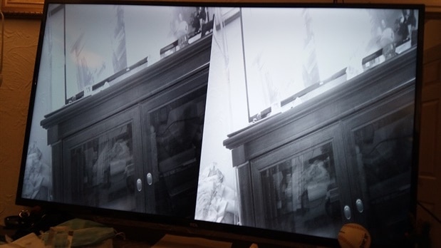
Testing the OOB under low light conditions. |
The OOB uses 1920x1080 resolution of of the box |
If you look closely there is some camera noise. |
Upon login one is met with the standard petalinux login. |
Stereo view |
 |
 |
The original resolution of 1920x1080p is not feasible for stereo applications. The computational resources to implement Stereo Local block matching with such a resolution go beyond the computational resources available on the Ultra96 board.
So the next logical step was to change the resolution of the individual images to VGA.
This requires editing the script that configures the gstreamer pipeline.
Changing resolution to VGA
run_1920_1080
media-ctl -d /dev/media0 -V '"ap1302.4-003c":0 [fmt:UYVY8_1X16/2560x800 field:none]'

media-ctl -d /dev/media0 -V '"a0020000.mipi_csi2_rx_subsystem":0 [fmt:UYVY8_1X16/2560x800 field:none]'
media-ctl -d /dev/media0 -V '"a0020000.mipi_csi2_rx_subsystem":1 [fmt:UYVY8_1X16/2560x800 field:none]'
media-ctl -d /dev/media0 -V  '"a0080000.v_proc_ss":0 [fmt:UYVY8_1X16/2560x800 field:none]'
media-ctl -d /dev/media0 -V  '"a0080000.v_proc_ss":1 [fmt:UYVY8_1X16/640x480 field:none]'
modetest -M xlnx -s 42:640x480@RG16 -P 38@40:640x480@YUYV -w 39:alpha:0 &
gst-launch-1.0 v4l2src device=/dev/video0 io-mode="dmabuf" ! "video/x-raw, width=640, height=480, format=YUY2, framerate=60/1" ! videoconvert ! kmssink plane-id=38 bus-id=fd4a0000.zynqmp-display render-rectangle="<0,0,640,480> fullscreen-overlay=true sync=false" -v
| {gallery} My Gallery Title |
|---|
REPLACE THIS TEXT WITH YOUR IMAGE IMAGE TITLE: THEN IMAGE DESCRIPTION |
REPLACE THIS TEXT WITH YOUR IMAGE IMAGE TITLE: THEN IMAGE DESCRIPTION |
 |
As you can see above , the original image is scaled from the orginal resolution.
After initializing the MIPI cores the data is passed through the video processing subsystem which converts to the appropriate format and does the scaling.
The video feed enumerates as a /video0 device under /dev.
This means one can use OpenCV or any other program to read the video feed once the gstreamer pipeline has started.
The OOB (Out of Box) image comes up with a script located under /usr/bin which configures the V4L2 pipeline and Gstreamer application to output the camera feed via the Displayport connector. To run it one has to issue
run_1920_1080
on the command line.
In this script both cameras are configured for 1080p resolution.
The only information one can glean about the camera is via the v4l2 API framework
| {gallery} My Gallery Title |
|---|
|
Planar YUV formats supported by the ISP |
I |
| {gallery} My Gallery Title |
|---|
|
|
|
|
|
Vivado Design
The Vivado hardware pipeline is composed of three blocks.
Block 1: This contains the ZYNQ MPSOC and reset IP
Block 2: This contains the MIPI CSI IP connected to the AP1302 and scaling IP together with a framebuffer write IP
Block 3: This contains the display output together with the timing generator and Video On Screen Display.
Vivado 2020.1 was setup on a virtual machine.
The design follows the steps outlined here:
Ultra96-V2 ON Semiconductor Dual Camera Mezzanine hardware build instructions
Ultra96-V2 Dual Camera Mezzanine Petalinux Build Instructions
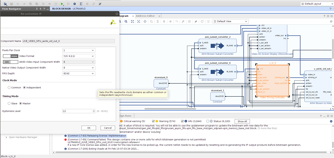
However It was observed that the bitstream generation fails due to the Video On Screen Display block (OSD).
As you can see below there is an issue with the licensing of the VOSD core when the webpack license is used.
| {gallery} My Gallery Title |
|---|
 |
 |
 |
 |
 |
Issue with OSD core |
OSD core has been deprecated |
Firmware
The kernel driver for the camera is under this link:
https://github.com/Avnet/ap1302-driver
There si only one other link on Gihub about this co-processor and even there there is no infomation on the ISP.
https://github.com/YashketGupta/PanaCast2-isp-fw
Since the generated Kernel of the OOB image already contains the AP1302 kernel driver , the next approach I took was to use PYNQ 2.6 rootFS filesystem together with the OOB image kernel. This did not work as expected even though the /dev/video enumerates.
It seems as there is an issue with the WIFI module on the OOB image kernel.
There is a reference design on Hackster :
https://www.hackster.io/adam-taylor/avnet-ultra96-and-onsemi-dual-mipi-camera-3492ab
however the author seems to have access to the SDK bare metal driver of the cameras and ISP chipset.
Without these it's not possible to have a working bare-metal implementation.
Software layer
The software layer makes use of the Video 4 Linux 2 framework and the Gstreamer API. The device enumerates as a video block device under /dev/video0

This allows one to read the video feed from a user-space application.
Unfortunately the OOB image does not include OpenCV. In addition it does not include the Vitis AI . PYNQ package was not possible to install due to issues with the WIFI connectivity.
After the U96 enumerates as an accesspoint and the WIFI network credentials are provided the connectivity still fails.
Stereo Application
The typical stereo application consists of four main general steps:
1. First there is the cost matching computation;
2 During the second step there is a cost aggregation;
3. Then a disparity selection is performed
4. The final step makes use of disparity refinement algorithms
No mechanical information has been published about the dual camera mezzanine regarding the camera distance from the center lines. This information is needed for depth inference once the stereo map is obtained.
The main difficulty implementing stereo application is that the video feed does not contain separate channels which must be sent concurrently to the Stereo IP core. Instead the video data from both channels is merged on the AP1302 ISP chip in one data stream where each of the camera feeds takes one virtual channel. This effectively requires either de-encapsulating the virtual video channels in hardware using VDMA or simply cropping the video feed in user-space and send each cropped camera feed to the Stereo core on the PL side.
Given the lack of documentation and ability to access individual camera feeds, implementing a stereo application is not straightforward or rather involves many more steps compared to a stereo camera jig.
Below , a typical stereo application using OpenCV python has been included. This however assumes that there are two /dev/video* devices one for each camera.
import numpy as np
import cv2
import argparse
import sys
from calibration_store import load_stereo_coefficients

def depth_map(imgL, imgR):
    """ Depth map calculation. Works with SGBM and WLS. Need rectified images, returns depth map ( left to right disparity ) """
    # SGBM Parameters -----------------
    window_size = 3  # wsize default 3; 5; 7 for SGBM reduced size image; 15 for SGBM full size image (1300px and above); 5 Works nicely

    left_matcher = cv2.StereoSGBM_create(
        minDisparity=-1,
        numDisparities=5*16,
        blockSize=window_size,
        P1=8 * 3 * window_size,
        # wsize default 3; 5; 7 for SGBM reduced size image; 15 for SGBM full size image (1300px and above); 5 Works nicely
        P2=32 * 3 * window_size,
        disp12MaxDiff=12,
        uniquenessRatio=10,
        speckleWindowSize=50,
        speckleRange=32,
        preFilterCap=63,
        mode=cv2.STEREO_SGBM_MODE_SGBM_3WAY
    )
    right_matcher = cv2.ximgproc.createRightMatcher(left_matcher)
    # FILTER Parameters
    lmbda = 80000
    sigma = 1.3
    visual_multiplier = 6

    wls_filter = cv2.ximgproc.createDisparityWLSFilter(matcher_left=left_matcher)
    wls_filter.setLambda(lmbda)

    wls_filter.setSigmaColor(sigma)
    displ = left_matcher.compute(imgL, imgR)  # .astype(np.float32)/16
    dispr = right_matcher.compute(imgR, imgL)  # .astype(np.float32)/16
    displ = np.int16(displ)
    dispr = np.int16(dispr)
    filteredImg = wls_filter.filter(displ, imgL, None, dispr)  # important to put "imgL" here!!!

    filteredImg = cv2.normalize(src=filteredImg, dst=filteredImg, beta=0, alpha=255, norm_type=cv2.NORM_MINMAX);
    filteredImg = np.uint8(filteredImg)

    return filteredImg


if __name__ == '__main__':
    # Args handling -> check help parameters to understand
    parser = argparse.ArgumentParser(description='Camera calibration')
    parser.add_argument('--calibration_file', type=str, required=True, help='Path to the stereo calibration file')
    parser.add_argument('--left_source', type=str, required=True, help='Left video or v4l2 device name')
    parser.add_argument('--right_source', type=str, required=True, help='Right video or v4l2 device name')
    parser.add_argument('--is_real_time', type=int, required=True, help='Is it camera stream or video')

    args = parser.parse_args()

    # is camera stream or video


        print("Can't opened the streams!")
        sys.exit(-9)

    # Change the resolution in need
    cap_right.set(cv2.CAP_PROP_FRAME_WIDTH, 640)  # float
    cap_right.set(cv2.CAP_PROP_FRAME_HEIGHT, 480)  # float

    cap_left.set(cv2.CAP_PROP_FRAME_WIDTH, 640)  # float
    cap_left.set(cv2.CAP_PROP_FRAME_HEIGHT, 480)  # float

    while True:  # Loop until 'q' pressed or stream ends
        # Grab&retreive for sync images
        if not (cap_left.grab() and cap_right.grab()):
            print("No more frames")
            break

        _, leftFrame = cap_left.retrieve()
        _, rightFrame = cap_right.retrieve()
        height, width, channel = leftFrame.shape  # We will use the shape for remap

        # Undistortion and Rectification part!
        leftMapX, leftMapY = cv2.initUndistortRectifyMap(K1, D1, R1, P1, (width, height), cv2.CV_32FC1)
        left_rectified = cv2.remap(leftFrame, leftMapX, leftMapY, cv2.INTER_LINEAR, cv2.BORDER_CONSTANT)
        rightMapX, rightMapY = cv2.initUndistortRectifyMap(K2, D2, R2, P2, (width, height), cv2.CV_32FC1)
        right_rectified = cv2.remap(rightFrame, rightMapX, rightMapY, cv2.INTER_LINEAR, cv2.BORDER_CONSTANT)

        # We need grayscale for disparity map.
        gray_left = cv2.cvtColor(left_rectified, cv2.COLOR_BGR2GRAY)
        gray_right = cv2.cvtColor(right_rectified, cv2.COLOR_BGR2GRAY)

        disparity_image = depth_map(gray_left, gray_right)  # Get the disparity map

        # Show the images
        cv2.imshow('left(R)', leftFrame)
        cv2.imshow('right(R)', rightFrame)
        cv2.imshow('Disparity', disparity_image)

        if cv2.waitKey(1) & 0xFF == ord('q'):  # Get key to stop stream. Press q for exit
            break

    # Release the sources.
    cap_left.release()
    cap_right.release()
    cv2.destroyAllWindows()
In order to use the camera mezannine with PYNQ or any stereo app the following may needs to be implemented:
a) revise design to use Mixer IP as opposed to VOSD
b) revise design to split virtual channels output into two separate AXIS streams
c) or use a VDMA to crop each L/R section of the MIPI output stream.
Verdict
The good
1. The cameras work. You get two images side by side.
2. There is a basic no-frills V42L driver.
3. The cameras can be replaced thanks to the 30 pin connectors , though there are no options for color cameras.
The bad
1. Camera configuration codes and datasheet are under NDA. No release possible unless you are a commercial entity. I asked the FAE to provide binary blobs or SDK driver if possible and did not hear from them.
2. ISP configuration code and datasheet are under NDA. This effectively makes it impossible to implement a bare-metal solution.
3. The ISP provides a single datastream encapsulating both images in virtual channels. No access to each video stream independently adds another difficulty to the implementation of a stereo algorithm .
4. As of February the ISP driver, kernel module is still under development.
5. The OOB image lacks the userspace software for a video solution (OpenCV, Vitis AI)
6. The OOB image looks like it has a problem with the WIFI chipset configuration
The nonsense
Datasheets for ISP and cameras are under NDA so if the kernel module is buggy or does not expose the functionality then reverse engineering is the answer.


Top Comments
Nice honest review.
I was hoping that the system would live up to its potential, but it looks like the hardware was rushed out before the support tools could be completed.
Sad, I was hoping to see a good…
I bought the Dual camera mezzanine a while ago. At the time the sample Vivado project and IP wasn't even publicly available but I managed to get a beta version. I'd hoped things had improved since then…
Without the datasheet and ISP sample and camera code it's not possible to get a baremetal design like it was done by Adam Taylor.
Even then it's not possible to get independent synchronous concurrent…
-

DAB
-
Cancel
-
Up
+2
Down
-
-
Reply
-
More
-
Cancel
Comment-

DAB
-
Cancel
-
Up
+2
Down
-
-
Reply
-
More
-
Cancel
Children