element14 Community
element14 Community
    Register Log In
  • Site
  • Search
  • Log In Register
  • Members
    Members
    • Achievement Levels
    • Benefits of Membership
    • Feedback and Support
    • Members Area
    • Personal Blogs
    • What's New on element14
  • Learn
    Learn
    • eBooks
    • Learning Center
    • Learning Groups
    • STEM Academy
    • Webinars, Training and Events
  • Technologies
    Technologies
    • 3D Printing
    • Experts & Guidance
    • FPGA
    • Industrial Automation
    • Internet of Things
    • Power & Energy
    • Sensors
    • Technology Groups
  • Challenges & Projects
    Challenges & Projects
    • Arduino Projects
    • Design Challenges
    • element14 presents
    • Project14
    • Project Groups
    • Raspberry Pi Projects
  • Products
    Products
    • Arduino
    • Avnet Boards Community
    • Dev Tools
    • Manufacturers
    • Product Groups
    • Raspberry Pi
    • RoadTests & Reviews
  • Store
    Store
    • Visit Your Store
    • Or choose another store...
      • Europe
      •  Austria (German)
      •  Belgium (Dutch, French)
      •  Bulgaria (Bulgarian)
      •  Czech Republic (Czech)
      •  Denmark (Danish)
      •  Estonia (Estonian)
      •  Finland (Finnish)
      •  France (French)
      •  Germany (German)
      •  Hungary (Hungarian)
      •  Ireland
      •  Israel
      •  Italy (Italian)
      •  Latvia (Latvian)
      •  
      •  Lithuania (Lithuanian)
      •  Netherlands (Dutch)
      •  Norway (Norwegian)
      •  Poland (Polish)
      •  Portugal (Portuguese)
      •  Romania (Romanian)
      •  Russia (Russian)
      •  Slovakia (Slovak)
      •  Slovenia (Slovenian)
      •  Spain (Spanish)
      •  Sweden (Swedish)
      •  Switzerland(German, French)
      •  Turkey (Turkish)
      •  United Kingdom
      • Asia Pacific
      •  Australia
      •  China
      •  Hong Kong
      •  India
      •  Korea (Korean)
      •  Malaysia
      •  New Zealand
      •  Philippines
      •  Singapore
      •  Taiwan
      •  Thailand (Thai)
      • Americas
      •  Brazil (Portuguese)
      •  Canada
      •  Mexico (Spanish)
      •  United States
      Can't find the country/region you're looking for? Visit our export site or find a local distributor.
  • Translate
  • Profile
RoadTests & Reviews
  • Products
  • More
RoadTests & Reviews
Documents Honeywell TruStability Digital pressure sensor review
  • Blog
  • RoadTest Forum
  • Documents
  • RoadTests
  • Reviews
  • Polls
  • Files
  • Members
  • Mentions
  • Sub-Groups
  • Tags
  • More
  • Cancel
  • New
RoadTests & Reviews requires membership for participation - click to join
Actions
  • Share
  • More
  • Cancel
Engagement
  • Author Author: R_Phoenix
  • Date Created: 14 Jan 2011 2:38 PM Date Created
  • Last Updated Last Updated: 9 Nov 2021 4:55 PM
  • Views 1501 views
  • Likes 0 likes
  • Comments 6 comments
Related
Recommended

Honeywell TruStability Digital pressure sensor review

Honeywell TruStability Digital pressure sensor review
 
Products:
HSCDANN001PGSA5 0 to 1 psi digital output
HSCDANN005PGSA5 0 to 5 psi digital output
 
image
 
Test Bed:
Mbed rapid proto typing Microcontroller
Arduino Microcontroller
 
Product Overview:
The sensors are packaged in a nice clean hard plastic shell that provides good protection during shipment.  The sensors themselves look and feel sturdy and appear to be able to handle small vibrations and shock.  There are a wide verity of mounting and tube connection types as well as 3.3 or 5 volts. They are available in Analog, I2C, or SPI digital communication.
 
Both sensors I looked at use the SPI Bus for communications and are 5 volts powered. Note that I was not familiar with the SPI bus before this evaluation, I thought I had requested the I2C versions – but that’s OK. I learned something new as well.
 
Product Documentation:
The Documentation was a bit time consuming to find. Honeywell likes to create documents that encompass an entire series of product, so I had to track down and piece together all the needed information. If you have ever navigated Honeywell’s web site, it can be overwhelming at times simply trying to find a specific product and as usual, entering the part number in the search box yielded 0 results. I prefer that all the needed information is on one data sheet.
 
Related documents:
http://sensing.honeywell.com/index.cfm/ci_id/157751/la_id/1/document/1/re_id/0
http://sensing.honeywell.com/index.cfm/ci_id/156989/la_id/1/document/1/re_id/0
http://sensing.honeywell.com/index.cfm/ci_id/156218/la_id/1/document/1/re_id/0
 
After spending a few hours gathering the needed information about how to program the needed SPI interface, I constructed a small test bed to test the sensors.
 
Basic Layout:
image
This image shows the Sensor connected to my small hand pump and analog mechanical gauge. This allows me to slowly apply pressure to the sensor and I can verify the pressure with the gauge against the sensor. The LED allows me to verify that the device is being selected, as the SS line goes low when reading data from the device.
image
Arduino Hook up
image
 
At this point I have to admit that my evaluation failed. The reason for this is unclear but I could not get the device to produce the proper information. This might be due to the fact that I’m too unfamiliar with the SPI interface, or possibly I am missing a key bit of information about the Honeywell SPI interface. I spent several hours talking to others and discussing the data and programming on other forums and after trying several things, everyone has run out of Ideas.
 
I want to post my results here for anyone else thinking about using these sensors so they can see everything that I have tried. Hopefully Someone here (or possibly from Honeywell) can spot the problem. Most likely I am missing something in the hookup or programming and the device operates just fine.
 
One issue I thought sure was the problem was the fact that the mbed MPU is 3.3 volts and possibly was not putting the proper voltage on the SCLK line. This is why I switched over to the Ardunio MPU. This uses 5 volts instead and should produce the needed 4 volts on the SCLK line – However as you will see the results were the same.
 
Programming:
mBed test program:

#include "mbed.h"
#define OUT_MAX 16384
#define OUT_MIN 0
#define PRES_MAX 5
#define PRES_MIN 0

SPI spi(p11, p12, p13); // mosi - no connection, miso - connected to pin 3 of sensor, sclk connected to pin 4 of sensor
DigitalOut cs(p8);   // chip Select line connected to pin 5 of sensor

Serial pc(p9,p10); // tx, rx

int main() {
    // Setup the spi for 8 bit data with a 800KHz clock rate
    spi.format(8,0);
    spi.frequency(500000);

    while(1)
    {
    // Select the device by seting chip select low
    cs = 0;
    wait_us(8);
    // Send a dummy byte to receive the contents
    int byte_1 = spi.write(0x00);
    int byte_2 = spi.write(0x00);
    int byte_3 = spi.write(0x00);
    int byte_4 = spi.write(0x00);
       
    float temp = byte_3<<3;
    temp = (temp*200/2047)-50;
    float psi = byte_1<<8|byte_2;
    psi = ((psi-OUT_MIN)*PRES_MAX)/(OUT_MAX-OUT_MIN);
   
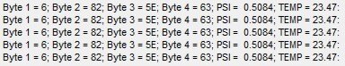
    pc.printf("Byte 1 = %X; Byte 2 = %X; Byte 3 = %X; Byte 4 = %X; PSI =  %.4f; TEMP = %.2f:\r",byte_1,byte_2,byte_3,byte_4,psi,temp);
   
    // Deselect the device
    cs = 1;
    wait(1);
    }
}

 
mbed results:
note: Byte_1 to Byte_4 are in HEX notation, PSI and TEMP are Dec
image
 
Ardunio Program:

#include <SPI.h>

// pins used for the connection with the sensor
// the other you need are controlled by the SPI library):
const int dataReadyPin = 6;
const int chipSelectPin = 7;

void setup() {
  Serial.begin(9600);

  // start the SPI library:
  SPI.begin();
  SPI.setClockDivider(128);
  // initalize the  data ready and chip select pins:
  pinMode(dataReadyPin, INPUT);
  pinMode(chipSelectPin, OUTPUT);
  digitalWrite(chipSelectPin,HIGH);
 
  delay(100);
}

void loop()
{
  digitalWrite(chipSelectPin,LOW);
  delay(10);
 
  int inByte_1 = SPI.transfer(0x00);
  int inByte_2 = SPI.transfer(0x00);
  int inByte_3 = SPI.transfer(0x00);
  int inByte_4 = SPI.transfer(0x00);
 
  Serial.print("Byte_1 = ");Serial.print(inByte_1,DEC);Serial.print(" ");
  Serial.print("Byte_2 = ");Serial.print(inByte_2,DEC);Serial.print(" ");
  Serial.print("Byte_3 = ");Serial.print(inByte_3,DEC);Serial.print(" ");
  Serial.print("Byte_4 = ");Serial.print(inByte_4,DEC);Serial.print(" ");
 
  float psi = inByte_1<<8|inByte_2;
  psi = (psi*5)/16384;
  Serial.print("PRES = ");Serial.print(psi);Serial.print(" ");
 
  inByte_3 = inByte_3<<3;
  float realTemp = ((float)inByte_3*200/2047)-50;
  Serial.print("Temp[C]= ");Serial.print(realTemp);Serial.print("\n");
  
  digitalWrite(chipSelectPin,HIGH);
  delay(1000); 
}

 
Arduino Results:

Note: all numbers are in Decimal notation.

image


The Problem:
The internal temperature was close, only 3 to 4 degrees off from Ambient temperature. I assume this to be correct as it is measuring the temp of the sensor itself and not ambient air (I don’t think). So my conclusion is that the electronics will warm a bit during use. I believe the Temperature to be correct.
 
However the Pressure was way off. The Documentation states the digital counts should be between (or near) 0x000 with 0 pressure and 0x3FFF at MAX Pressure +/- Atmospheric. I was unable to achieve either value. In fact the most the digital count changed between 0 and 5psi was about 450 counts. Not near enough to be highly accurate.
 
What I have tried:
I have tried all formats, 8,0 8,1 8,2 and 8,3 as well as 16 bit vs 8 bit
I have tried reading all data in a single string instead of pinging the register 4 separate times.
I have tried all possible clock frequencies.
One thing myself and other could not find in the documentation was any mention of a specified register address that I must read first. This lead me to believe that there was none.
I have tried several different values for the OUTPUT Max and the OUTPUT Min including those listed in the documentation.
I have tried decoupling the power lines.
All of these things would affect the output data, but not make it correct.
 
In conclusion:
Because I was unable to test these sensors successfully I cannot comment on their stability, function, or accuracy.  Currently I use the ADMS series of Honeywell Analog sensors and those work great and are Highly accurate. I can measure water levels down to 0.25” accuracy and could get it even further if I needed to.  Unfortunately I was unable to test the HCS series in this application. If anyone might have ideas on what I am doing wrong, please message me and I will update this document with any new developments.
  • spi
  • pressure_sensor
  • honeywell
  • hsc
  • Design Resources
  • Share
  • History
  • More
  • Cancel
  • Sign in to reply
  • R_Phoenix
    R_Phoenix over 11 years ago in reply to mookiebud

    Thanks for the tips, but yah - it's been a while. I have since moved to an analog True Stability sensor. Just like these but Analog. I'm now useing a 0 - 160 mBar ( ~ 0 to 2.5 psi). It works well and it is a direct replacement (almost) from the ADX series.

    • Cancel
    • Vote Up 0 Vote Down
    • Sign in to reply
    • More
    • Cancel
  • mookiebud
    mookiebud over 11 years ago

    My bad, I see that it was over a year ago you posted. Looks I assumed a more recent date because of the list position in the documents section. As I said, my bad but hopefully the info helps someone.

    • Cancel
    • Vote Up 0 Vote Down
    • Sign in to reply
    • More
    • Cancel
  • mookiebud
    mookiebud over 11 years ago

    Eewww, sorry for the font thing. I wrote the reply up on 2 separate occasions in a note app and it appears to have messed with the font when I copied and pasted. My apologies....

    • Cancel
    • Vote Up 0 Vote Down
    • Sign in to reply
    • More
    • Cancel
  • mookiebud
    mookiebud over 11 years ago

    Hi R_Pheonix,


    I just came across your review and read it as I am looking into the arduino platform and have a background in pressure sensors, although most are analog ones that I have used. That being said I noticed a couple of things that I hope might help.


    First, are you sure the SPI phase and clock polarity are correct? Usually when I observe the same data, over and over, it is usually related to clock and data phase settings not being correct. I noticed in your arduino code you don't specifically call out a function to set this up. Perhaps the defaults are OK as I mentioned, I'm looking into the arduino platform but actually have never used it.  I have used lots of SPI devices in the past however. The on line doc's don't mention what the default would be so I would assume it's the chips default state.


    In looking at the (sensor) datasheet, and I hate datasheets that aren't clear, it would appear you would need to set the SPI to mode 3. The datasheet mentions, " ... that data on the MISO line will transition during the falling edge of clock pulses. This means that the data on MISO should be sampled by the master device during the rising edge of the clock pulse."   This could be either Mode 1 or Mode 3 depending on if the initial bit is placed on the MISO line when the SS drops. The diagram ("

    Figure 2. Example of a 1 Byte SPI Data Transfer with Honeywell Pressure Sensors") shows a low clock when initiating, and a high clock when completeing which is the 'clarity' issue I mentioned in the beginning.  From the wording, I would try Mode 3 and see if your data changes and reflects a more accurate picture.


    <comment> In your data, you mentioned temperature is 'close',  but have you tried heating the sensor to see if your data changes? I would expect even a warming with the touch of your finger should show a change in your data. If it does not, then I expect the SPI phase/mode is not correct </comment>


    So, lets assume for a moment that your raw SPI data *is* correct. I think your calculation assumes a 14 bit part per the Honeywell SPI doc you linked to, and further, you assume ideal 0 -100% measurement in your calculation. To go one step further, the part datasheet link you included actually specifies a 12 bit part and therefore I think your data calc should be a bit different ...


    Outputmax = 3686 counts (90% of 2^12 counts or 0xE66)

    Outputmin = 409 counts (10% of 2^12 counts or 0x199)

    Pressuremax = 5 psi

    Pressuremin = 0 psi

    Pressure = pressure in psi

    Output = 1668 counts (from your data listed above  0x684)


    should yield a pressure of ....  p = ((1668-409)*5) / (3686-409) = 1.921 which is quite different than your printed pressure.


    My final comment would be that the device datasheet appears to say that the device will work with either 3.3 or 5 V and I would expect the sensor to respond to either voltage. You mentioned your data was the same, and this I would expect if the device operates at both voltages.


    So, hopefully that helps although I note it's been a while since you posted the original and updates.

    • Cancel
    • Vote Up 0 Vote Down
    • Sign in to reply
    • More
    • Cancel
  • R_Phoenix
    R_Phoenix over 12 years ago

    I should also mention that these results were the same for both sensors types that I tested.

    • Cancel
    • Vote Up 0 Vote Down
    • Sign in to reply
    • More
    • Cancel
element14 Community

element14 is the first online community specifically for engineers. Connect with your peers and get expert answers to your questions.

  • Members
  • Learn
  • Technologies
  • Challenges & Projects
  • Products
  • Store
  • About Us
  • Feedback & Support
  • FAQs
  • Terms of Use
  • Privacy Policy
  • Legal and Copyright Notices
  • Sitemap
  • Cookies

An Avnet Company © 2023 Premier Farnell Limited. All Rights Reserved.

Premier Farnell Ltd, registered in England and Wales (no 00876412), registered office: Farnell House, Forge Lane, Leeds LS12 2NE.

ICP 备案号 10220084.

Follow element14

  • X
  • Facebook
  • linkedin
  • YouTube