element14 Community
element14 Community
    Register Log In
  • Site
  • Search
  • Log In Register
  • About Us
  • Community Hub
    Community Hub
    • What's New on element14
    • Feedback and Support
    • Benefits of Membership
    • Personal Blogs
    • Members Area
    • Achievement Levels
  • Learn
    Learn
    • Ask an Expert
    • eBooks
    • element14 presents
    • Learning Center
    • Tech Spotlight
    • STEM Academy
    • Webinars, Training and Events
    • Learning Groups
  • Technologies
    Technologies
    • 3D Printing
    • FPGA
    • Industrial Automation
    • Internet of Things
    • Power & Energy
    • Sensors
    • Technology Groups
  • Challenges & Projects
    Challenges & Projects
    • Design Challenges
    • element14 presents Projects
    • Project14
    • Arduino Projects
    • Raspberry Pi Projects
    • Project Groups
  • Products
    Products
    • Arduino
    • Avnet Boards Community
    • Dev Tools
    • Manufacturers
    • Multicomp Pro
    • Product Groups
    • Raspberry Pi
    • RoadTests & Reviews
  • Store
    Store
    • Visit Your Store
    • Choose another store...
      • Europe
      •  Austria (German)
      •  Belgium (Dutch, French)
      •  Bulgaria (Bulgarian)
      •  Czech Republic (Czech)
      •  Denmark (Danish)
      •  Estonia (Estonian)
      •  Finland (Finnish)
      •  France (French)
      •  Germany (German)
      •  Hungary (Hungarian)
      •  Ireland
      •  Israel
      •  Italy (Italian)
      •  Latvia (Latvian)
      •  
      •  Lithuania (Lithuanian)
      •  Netherlands (Dutch)
      •  Norway (Norwegian)
      •  Poland (Polish)
      •  Portugal (Portuguese)
      •  Romania (Romanian)
      •  Russia (Russian)
      •  Slovakia (Slovak)
      •  Slovenia (Slovenian)
      •  Spain (Spanish)
      •  Sweden (Swedish)
      •  Switzerland(German, French)
      •  Turkey (Turkish)
      •  United Kingdom
      • Asia Pacific
      •  Australia
      •  China
      •  Hong Kong
      •  India
      •  Korea (Korean)
      •  Malaysia
      •  New Zealand
      •  Philippines
      •  Singapore
      •  Taiwan
      •  Thailand (Thai)
      • Americas
      •  Brazil (Portuguese)
      •  Canada
      •  Mexico (Spanish)
      •  United States
      Can't find the country/region you're looking for? Visit our export site or find a local distributor.
  • Translate
  • Profile
  • Settings
555 Timers
  • Technologies
  • More
555 Timers
Forum Understanding 555 timer in astable mode but stuck on capacitors
  • Blog
  • Forum
  • Documents
  • Polls
  • Files
  • Members
  • Mentions
  • Sub-Groups
  • Tags
  • More
  • Cancel
  • New
Join 555 Timers to participate - click to join for free!
Actions
  • Share
  • More
  • Cancel
Forum Thread Details
  • State Verified Answer
  • Replies 14 replies
  • Answers 7 answers
  • Subscribers 53 subscribers
  • Views 8340 views
  • Users 0 members are here
  • capacitor
  • 555 timer
Related

Understanding 555 timer in astable mode but stuck on capacitors

opalko
opalko over 4 years ago

So I am still plowing my way through Platt's Make: Electronics and into chapter 4 working with the 555 timer IC.  The astable mode of the timer is giving me trouble as I don't understand how


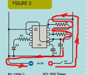
When C1 acquires 2/3 of the positive voltage powering the circuit, the 555 reverses its output on Pin 3 from positive to negative and forces C1 to discharge itself through R2.

(This last sentence is actually from Make Magazine issue 10 where Platt is explaining the same thing as in chapter 4 of his book - see image below)


image


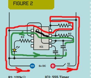
What I am confused about is the discharging through R2.  I am obviously stuck on what is going on with C1. As I understand it, it first gains a positive charge on what I will call the top plate in the picture above, and a negative charge on the bottom plate (next to where the label C1 is).  Maybe I have read too many analogies of water with electricity but I think of the capacitor as a balloon (in fact there are many analogies in Platt's book like this).  So how is the balloon releasing the pressure in what seems like a reverse direction back through R2?  Here is a similar circuit I found on circuitlab albeit the pins arranged differently and it shows that reversing of "flow":


image


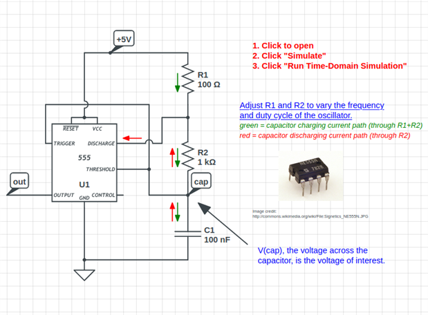
Is there not +5V into R2 from R1 at the same time C1 is discharging??

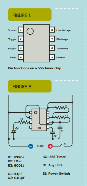
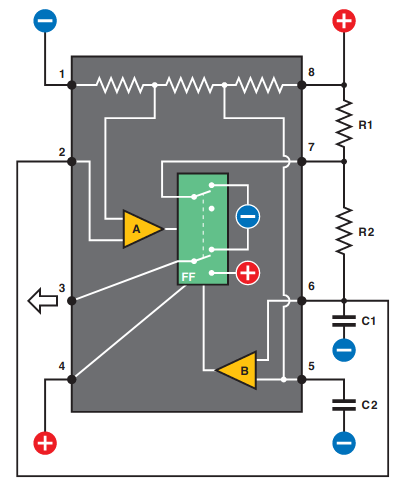
Finally here is Platt's "internal" view of the 555 timer in astable mode.  I assume pin 7 gets grounded to pin 3 but I am still confused about the seemingly reversal of flow through R2.


image

I've read through this many times and still stuck. Any additional help is appreciated!


Cheers


Message was edited by: Robert Opalko same day

  • Sign in to reply
  • Cancel

Top Replies

  • jw0752
    jw0752 over 4 years ago +6 verified
    Hi Robert, During the discharge part of the cycle the Pin 7 is attached to ground. (see the blue - in the last picture). Once pin 7 is connected to Ground the electricity in C1 starts to move through R2…
  • jw0752
    jw0752 over 4 years ago in reply to opalko +6 suggested
    Hi Robert, The polarized capacitors must be used in the correct polarity as they will fail if more than a token voltage is applied in the reverse direction. The polarity on the capacitor is not like that…
  • jw0752
    jw0752 over 4 years ago +5
    PS you are doing an excellent job of presenting your questions. I would bet that several times you have actually answered them yourself in the process of preparing the question. John
Parents
  • jc2048
    0 jc2048 over 4 years ago

    When you charge a capacitor, the increasing imbalance of charge causes the voltage between the plates to increase and

    the resulting electric field between the plates then stores energy. When you discharge the capacitor, that

    energy is then powering the discharge circuit.


    Personally, I don't much like bucket [water] and balloon [air] analogies. A capacitor isn't simply a

    container that you to pour something in to. When you add charge to one plate, you always remove the same

    charge from the other. It's the resulting imbalance between the two that stores energy and it can be either

    way round (leading to a voltage in either direction across the capacitor). Negative amounts of water and

    negative pressures are a bit weird, when you think about it. [Yes, the maths works with 'negative water'

    too, but what's the point? You're then struggling to explain an analogy that's supposed to make things

    easier to understand.]


    When we charge or discharge a capacitor, that flow of charge constitutes a current. Current paths are loops

    'driven' by voltage sources.


    Here is the current path [red] when the capacitor charges


    image


    and here is what happens when the 555 connects pin 7 to ground [black] and the capacitor discharges


    image


    There are now two paths. The current through R1 [red] now flows back to the supply through the 555. At the

    same time, the capacitor voltage drives a current through R2 [green] that returns to the other side of the

    capacitor through the 555. That current discharges the capacitor. [As it discharges, the voltage across the

    capacitor reduces until it reaches the lower threshold, at one third the supply voltage, at which point the

    555 removes the connection from pin 7 to gound and the capacitor starts charging again.]

    • Cancel
    • Vote Up +5 Vote Down
    • Sign in to reply
    • Verify Answer
    • Reject Answer
    • Cancel
Reply
  • jc2048
    0 jc2048 over 4 years ago

    When you charge a capacitor, the increasing imbalance of charge causes the voltage between the plates to increase and

    the resulting electric field between the plates then stores energy. When you discharge the capacitor, that

    energy is then powering the discharge circuit.


    Personally, I don't much like bucket [water] and balloon [air] analogies. A capacitor isn't simply a

    container that you to pour something in to. When you add charge to one plate, you always remove the same

    charge from the other. It's the resulting imbalance between the two that stores energy and it can be either

    way round (leading to a voltage in either direction across the capacitor). Negative amounts of water and

    negative pressures are a bit weird, when you think about it. [Yes, the maths works with 'negative water'

    too, but what's the point? You're then struggling to explain an analogy that's supposed to make things

    easier to understand.]


    When we charge or discharge a capacitor, that flow of charge constitutes a current. Current paths are loops

    'driven' by voltage sources.


    Here is the current path [red] when the capacitor charges


    image


    and here is what happens when the 555 connects pin 7 to ground [black] and the capacitor discharges


    image


    There are now two paths. The current through R1 [red] now flows back to the supply through the 555. At the

    same time, the capacitor voltage drives a current through R2 [green] that returns to the other side of the

    capacitor through the 555. That current discharges the capacitor. [As it discharges, the voltage across the

    capacitor reduces until it reaches the lower threshold, at one third the supply voltage, at which point the

    555 removes the connection from pin 7 to gound and the capacitor starts charging again.]

    • Cancel
    • Vote Up +5 Vote Down
    • Sign in to reply
    • Verify Answer
    • Reject Answer
    • Cancel
Children
  • opalko
    0 opalko over 4 years ago in reply to jc2048

    Thank you for this, so it would not matter in this example if the cacpacitor was polarized or non-polarized?  I guess that is the part I am struggling with.  I think I was thinking of a capacitor like a diode with the charge only flowing in one direction but this doesn't appear to be the case.  And also, why do we use polarized caps instead if it doesn't matter? 
    Thank you for the reply!
    Cheers

    • Cancel
    • Vote Up +3 Vote Down
    • Sign in to reply
    • Verify Answer
    • Cancel
  • Jan Cumps
    0 Jan Cumps over 4 years ago in reply to jc2048
    'negative water'


    I'm not a big fan of the analogy either, but it helps to get the discussion started.

    I try to explain negative water with a "very empty" bucket. Again not a good example, just a hook to get the discussion going without having the attendee's eyes glaze over or have them walk away after a few seconds.

    • Cancel
    • Vote Up +3 Vote Down
    • Sign in to reply
    • Verify Answer
    • Reject Answer
    • Cancel
  • jc2048
    0 jc2048 over 4 years ago in reply to opalko

    so it would not matter in this example if the cacpacitor was polarized or non-polarized?

    For this circuit, the voltage at the top plate of the capacitor always remains between the supply voltages, so it's always more positive that the end connected to ground and there's no problem using a polarised capacitor.


    why do we use polarized caps instead if it doesn't matter?

    If you want long timing intervals [slow oscillations], you need high values of capacitance, and electrolytics are the cheap way to do that.

    • Cancel
    • Vote Up +3 Vote Down
    • Sign in to reply
    • Verify Answer
    • Reject Answer
    • Cancel
  • opalko
    0 opalko over 4 years ago in reply to jc2048

    Thanks for the electrolytics explanation regarding, it helps!

    • Cancel
    • Vote Up +2 Vote Down
    • Sign in to reply
    • Verify Answer
    • Cancel
  • jc2048
    0 jc2048 over 4 years ago in reply to opalko

    I've just found a bag with some 555s in, so I thought I'd show you the voltage across C1 in the

    circuit of 'Figure 2'.


    image


    I chose a supply voltage of 6V so that the lower and upper thresholds would be 2V and 4V (the

    thresholds, unless you modify them, are 1/3 and 2/3 of the supply voltage), as that makes it

    easy to consider on the oscilloscope trace.


    You can see that the voltage across the capacitor always remains positive [the '1' channel

    marker on the left of the grid shows where 'ground' [zero volts] is, and the vertical scale is 1V per

    division], so it would be possible to use a polarised capacitor here.


    When the capacitor is charging, the voltage goes up, and as it discharges, it goes down.

    • Cancel
    • Vote Up +4 Vote Down
    • Sign in to reply
    • Verify Answer
    • Reject Answer
    • Cancel
  • opalko
    0 opalko over 4 years ago in reply to jc2048

    This is cool and makes me want an oscilloscope of my own!

    • Cancel
    • Vote Up +1 Vote Down
    • Sign in to reply
    • Verify Answer
    • Cancel
element14 Community

element14 is the first online community specifically for engineers. Connect with your peers and get expert answers to your questions.

  • Members
  • Learn
  • Technologies
  • Challenges & Projects
  • Products
  • Store
  • About Us
  • Feedback & Support
  • FAQs
  • Terms of Use
  • Privacy Policy
  • Legal and Copyright Notices
  • Sitemap
  • Cookies

An Avnet Company © 2025 Premier Farnell Limited. All Rights Reserved.

Premier Farnell Ltd, registered in England and Wales (no 00876412), registered office: Farnell House, Forge Lane, Leeds LS12 2NE.

ICP 备案号 10220084.

Follow element14

  • X
  • Facebook
  • linkedin
  • YouTube