element14 Community
element14 Community
    Register Log In
  • Site
  • Search
  • Log In Register
  • About Us
  • Community Hub
    Community Hub
    • What's New on element14
    • Feedback and Support
    • Benefits of Membership
    • Personal Blogs
    • Members Area
    • Achievement Levels
  • Learn
    Learn
    • Ask an Expert
    • eBooks
    • element14 presents
    • Learning Center
    • Tech Spotlight
    • STEM Academy
    • Webinars, Training and Events
    • Learning Groups
  • Technologies
    Technologies
    • 3D Printing
    • FPGA
    • Industrial Automation
    • Internet of Things
    • Power & Energy
    • Sensors
    • Technology Groups
  • Challenges & Projects
    Challenges & Projects
    • Design Challenges
    • element14 presents Projects
    • Project14
    • Arduino Projects
    • Raspberry Pi Projects
    • Project Groups
  • Products
    Products
    • Arduino
    • Avnet Boards Community
    • Dev Tools
    • Manufacturers
    • Multicomp Pro
    • Product Groups
    • Raspberry Pi
    • RoadTests & Reviews
  • Store
    Store
    • Visit Your Store
    • Choose another store...
      • Europe
      •  Austria (German)
      •  Belgium (Dutch, French)
      •  Bulgaria (Bulgarian)
      •  Czech Republic (Czech)
      •  Denmark (Danish)
      •  Estonia (Estonian)
      •  Finland (Finnish)
      •  France (French)
      •  Germany (German)
      •  Hungary (Hungarian)
      •  Ireland
      •  Israel
      •  Italy (Italian)
      •  Latvia (Latvian)
      •  
      •  Lithuania (Lithuanian)
      •  Netherlands (Dutch)
      •  Norway (Norwegian)
      •  Poland (Polish)
      •  Portugal (Portuguese)
      •  Romania (Romanian)
      •  Russia (Russian)
      •  Slovakia (Slovak)
      •  Slovenia (Slovenian)
      •  Spain (Spanish)
      •  Sweden (Swedish)
      •  Switzerland(German, French)
      •  Turkey (Turkish)
      •  United Kingdom
      • Asia Pacific
      •  Australia
      •  China
      •  Hong Kong
      •  India
      •  Korea (Korean)
      •  Malaysia
      •  New Zealand
      •  Philippines
      •  Singapore
      •  Taiwan
      •  Thailand (Thai)
      • Americas
      •  Brazil (Portuguese)
      •  Canada
      •  Mexico (Spanish)
      •  United States
      Can't find the country/region you're looking for? Visit our export site or find a local distributor.
  • Translate
  • Profile
  • Settings
555 Timers
  • Technologies
  • More
555 Timers
Forum Bounce Servo with 555 timer
  • Blog
  • Forum
  • Documents
  • Polls
  • Files
  • Members
  • Mentions
  • Sub-Groups
  • Tags
  • More
  • Cancel
  • New
Join 555 Timers to participate - click to join for free!
Actions
  • Share
  • More
  • Cancel
Forum Thread Details
  • State Verified Answer
  • Replies 12 replies
  • Subscribers 51 subscribers
  • Views 4507 views
  • Users 0 members are here
Related

Bounce Servo with 555 timer

Eric
Eric over 3 years ago

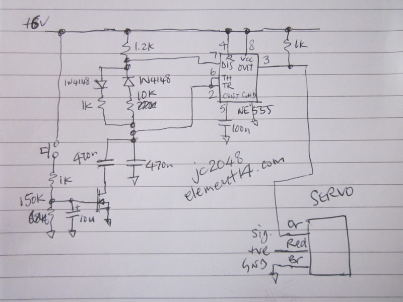
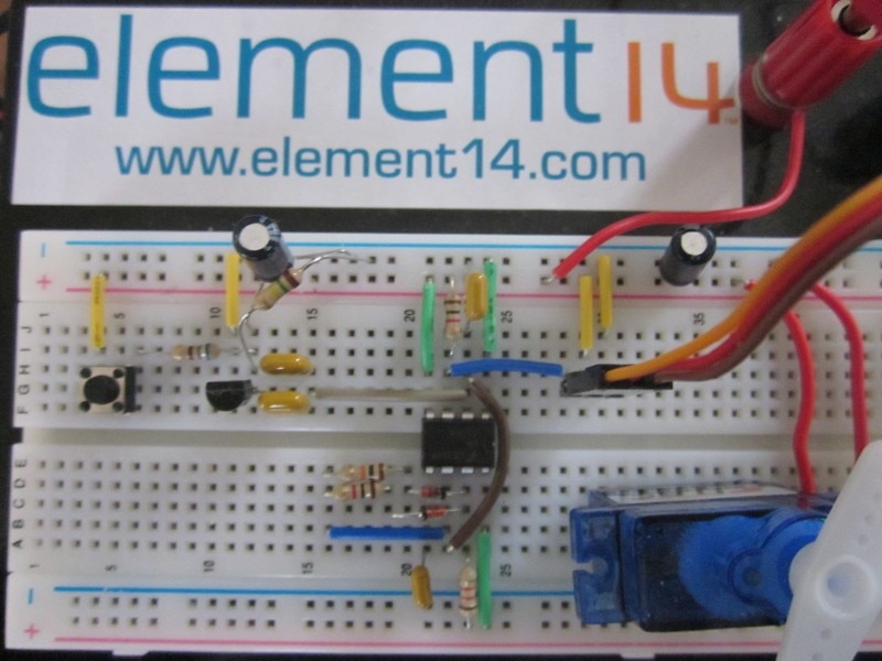
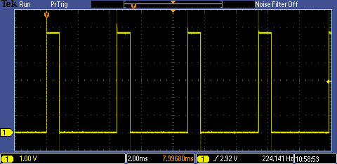
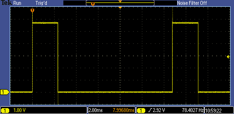
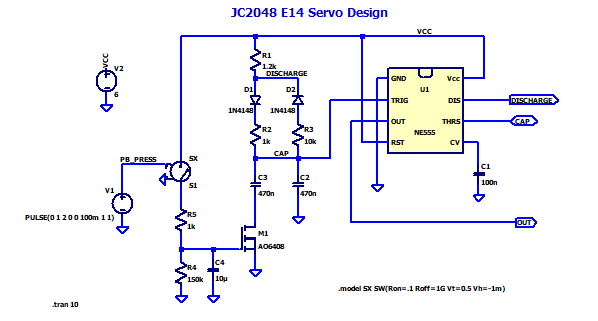
I want to toggle a servo with the push(and release) of a button.  I then want the servo to return to original position after x seconds.  I think I'm close by enlisting a 555 timer.  I have it successfully powering an LED for 1 second. (hold your applause)

Is this at least possible with this same circuit?  This is just a hobby project and I was trying to avoid grabbing an Arduino and coding something.

When I tried to connect my servo to pin 3, positive, and negative....it moved slightly once out of 10 attempts.  The LED is dimmer and shorter lived while the servo is attached.  

I should check back in here at least once a day until I get this working (and will report so) or smash the thing with a bat.

-EP

Some details...may be garbage.  THANKS IN ADVANCE!

Power = old 9v battery (8v)
Resistors = 10k
Cap = 100uf

  • Sign in to reply
  • Cancel

Top Replies

  • jc2048
    jc2048 over 3 years ago +4 verified
    Does this do what you wanted (sorry the video is a bit blurry)? community.element14.com/.../7411.MVI_5F00_3478.MOV Here's the circuit and the build on a breadboard the start position is controlled…
  • scottiebabe
    scottiebabe over 3 years ago in reply to jc2048 +3
    Neat little circuit. I wonder if I can upload .asc files on the new website. In the holiday spirit I put JC2048's deign into LTSpice for one to experiment with too. community.element14.com/.../1641.JC2048Servo…
  • dougw
    dougw over 3 years ago +2
    As @ scottiebabe points out it is a bit tricky but possible to do with 555 timers. You could make the middle waveform with a 556 (dual 555) - one 555 would generate a continuous square wave with 20 ms…
  • scottiebabe
    0 scottiebabe over 3 years ago

    Is it possible? Yes. Would I recommend a 555 for this application, no.

    Consider that you will need to generate a PWM waveform sweeping from a 5% dutycycle to 10% dutycyle depending on the servo.

    image

    • Cancel
    • Vote Up +1 Vote Down
    • Sign in to reply
    • Verify Answer
    • Cancel
  • dougw
    0 dougw over 3 years ago

    As @scottiebabe points out it is a bit tricky but possible to do with 555 timers. You could make the middle waveform with a 556 (dual 555) - one 555 would generate a continuous square wave with 20 ms period. The second 555 would be a one-shot triggered by the first 555 - it creates the 2 ms pulse shown in the middle waveform. A third 555 would be used to generate a 1 second pulse when the button is pushed to change positions. The output of the third 555 would drive a diode and resistor connected to the timing capacitor of 555 #2 so that its pulse width changes to 1 ms for one second. (the last waveform)

    It can also be done with just two 555s but the frequency might vary a bit.

    • Cancel
    • Vote Up +2 Vote Down
    • Sign in to reply
    • Verify Answer
    • Cancel
  • Eric
    0 Eric over 3 years ago in reply to scottiebabe

    Is there a more elegant solution to this?  I have only touched the surface of small electronics and may have got hung up on the name 'timer' thinking that was the best solution.  I also saw something of interest where the servo was physically modified and performed without pwm.

    • Cancel
    • Vote Up +1 Vote Down
    • Sign in to reply
    • Verify Answer
    • Cancel
  • scottiebabe
    0 scottiebabe over 3 years ago in reply to Eric

    Beauty is in the eye of the beholder. If you decide to use 555 timers you could submit your design to the 555 timer contest on hackaday.

    I recently used a RPI Pico to enable a PWM output after a button press it was too easy. Just a few lines a code and done.

    image

    A little microcontroller is a reasonable solution. The only challenge with the 555 or discrete logic in general is it isn't a cookbook application and may be a bit daunting depending on your experience.

    • Cancel
    • Vote Up +1 Vote Down
    • Sign in to reply
    • Verify Answer
    • Cancel
  • Eric
    0 Eric over 3 years ago in reply to scottiebabe

    Thanks for the feedback.  I am pursuing it with an Arduino now.  I can picture the final project having user input of pushing the button more than once to adjust the delay.  I did learn a touch along the way though.  Hoping to post in here with a completed project before 2022. 

    • Cancel
    • Vote Up +2 Vote Down
    • Sign in to reply
    • Verify Answer
    • Cancel
  • scottiebabe
    0 scottiebabe over 3 years ago in reply to Eric

    Sounds like a fun project. If you hit any snags, there are lots of members happy to help. Happy making!

    • Cancel
    • Vote Up +2 Vote Down
    • Sign in to reply
    • Verify Answer
    • Cancel
  • jc2048
    0 jc2048 over 3 years ago in reply to dougw

    If you were to use a MOSFET as a crude monostable, with resistor, capacitor, and switch, for the seconds timing, it could be done with just one 555 for the servo waveforms. I don't think the frequency variation matters with a servo (within limits, of course) - it's only looking for the pulse width.

    • Cancel
    • Vote Up +1 Vote Down
    • Sign in to reply
    • Verify Answer
    • Cancel
  • jc2048
    +1 jc2048 over 3 years ago

    Does this do what you wanted (sorry the video is a bit blurry)?

    Video processing failed.
    You don't have permission to edit metadata of this video.

    Here's the circuit and the build on a breadboard

    image

    image


    the start position is controlled by the 1k resistor under the 1N4148, the end position by the 470n capacitor
    controlled by the MOSFET (I actually used two 470n in parallel, so the circuit value's wrong), and the delay time
    after the switch is released is set by the 150k and the 10u.

    These are the output waveforms going to the servo, in case you're interested. First is the rest position, the second
    the position when the switch is pressed.

    image

    image

    Anyway, it will give you something to play with if you're interested in experimenting with a 555.

    • Cancel
    • Vote Up +4 Vote Down
    • Sign in to reply
    • Reject Answer
    • Cancel
  • scottiebabe
    0 scottiebabe over 3 years ago in reply to jc2048

    Neat little circuit. I wonder if I can upload .asc files on the new website. In the holiday spirit I put JC2048's deign into LTSpice for one to experiment with too.

    Fullscreen 1641.JC2048Servo.asc.txt Download
    Version 4
    SHEET 1 880 792
    WIRE -320 -32 -544 -32
    WIRE 0 -32 -320 -32
    WIRE 192 -32 0 -32
    WIRE 368 -32 192 -32
    WIRE -320 0 -320 -32
    WIRE -320 96 -320 80
    WIRE -224 96 -320 96
    WIRE -192 96 -224 96
    WIRE 80 96 48 96
    WIRE 368 96 368 -32
    WIRE 368 96 304 96
    WIRE -320 128 -320 96
    WIRE -192 128 -192 96
    WIRE 80 160 -96 160
    WIRE 448 160 304 160
    WIRE -768 176 -768 144
    WIRE -320 224 -320 192
    WIRE -192 224 -192 192
    WIRE 80 224 -32 224
    WIRE 448 224 304 224
    WIRE 0 288 0 -32
    WIRE 80 288 0 288
    WIRE 352 288 304 288
    WIRE -544 336 -544 -32
    WIRE -320 336 -320 304
    WIRE -240 336 -320 336
    WIRE -192 336 -192 304
    WIRE -192 336 -240 336
    WIRE -96 336 -96 160
    WIRE -96 336 -192 336
    WIRE -592 352 -720 352
    WIRE 352 352 352 288
    WIRE -320 384 -320 336
    WIRE -192 384 -192 336
    WIRE 48 416 48 96
    WIRE -720 432 -720 352
    WIRE 352 448 352 416
    WIRE -544 480 -544 416
    WIRE -192 512 -192 448
    WIRE -320 528 -320 448
    WIRE -32 528 -32 224
    WIRE 464 528 -32 528
    WIRE -720 544 -720 512
    WIRE -544 608 -544 560
    WIRE -448 608 -544 608
    WIRE -368 608 -448 608
    WIRE -544 640 -544 608
    WIRE -448 640 -448 608
    WIRE -320 672 -320 624
    WIRE -544 752 -544 720
    WIRE -448 752 -448 704
    FLAG 48 416 0
    FLAG 352 448 0
    FLAG 192 -32 VCC
    FLAG 448 160 DISCHARGE
    IOPIN 448 160 Out
    FLAG -192 512 0
    FLAG -320 672 0
    FLAG -240 336 CAP
    FLAG 448 224 CAP
    IOPIN 448 224 BiDir
    FLAG 464 528 OUT
    IOPIN 464 528 Out
    FLAG -544 752 0
    FLAG -448 752 0
    FLAG -592 400 0
    FLAG -768 176 0
    FLAG -720 544 0
    FLAG -768 64 VCC
    FLAG -224 96 DISCHARGE
    SYMBOL Misc\\NE555 192 192 R0
    SYMATTR InstName U1
    SYMBOL cap 336 352 R0
    SYMATTR InstName C1
    SYMATTR Value 100n
    SYMBOL res -336 -16 R0
    SYMATTR InstName R1
    SYMATTR Value 1.2k
    SYMBOL res -336 208 R0
    SYMATTR InstName R2
    SYMATTR Value 1k
    SYMBOL res -208 208 R0
    SYMATTR InstName R3
    SYMATTR Value 10k
    SYMBOL diode -304 128 M0
    SYMATTR InstName D1
    SYMATTR Value 1N4148
    SYMBOL diode -176 192 R180
    WINDOW 0 24 64 Left 2
    WINDOW 3 24 0 Left 2
    SYMATTR InstName D2
    SYMATTR Value 1N4148
    SYMBOL cap -208 384 R0
    SYMATTR InstName C2
    SYMATTR Value 470n
    SYMBOL cap -336 384 R0
    SYMATTR InstName C3
    SYMATTR Value 470n
    SYMBOL nmos -368 528 R0
    SYMATTR InstName M1
    SYMATTR Value AO6408
    SYMBOL cap -464 640 R0
    SYMATTR InstName C4
    SYMATTR Value 10�
    SYMBOL res -560 624 R0
    SYMATTR InstName R4
    SYMATTR Value 150k
    SYMBOL res -560 464 R0
    SYMATTR InstName R5
    SYMATTR Value 1k
    SYMBOL sw -544 432 M180
    SYMATTR InstName S1
    SYMATTR Value SX
    SYMBOL voltage -720 416 M0
    WINDOW 123 0 0 Left 0
    WINDOW 39 0 0 Left 0
    SYMATTR InstName V1
    SYMATTR Value PULSE(0 1 2 0 0 100m 1 1)
    SYMBOL voltage -768 48 R0
    WINDOW 123 0 0 Left 0
    WINDOW 39 0 0 Left 0
    SYMATTR InstName V2
    SYMATTR Value 6
    TEXT -72 728 Left 2 !.model SX SW(Ron=.1 Roff=1G Vt=0.5 Vh=1m)
    TEXT -930 776 Left 2 !.tran 10
    TEXT -392 -104 Left 4 ;JC2048 E14 Servo Design
    

    No luck with .asc, I had to add a .txt extension.

    image

    image

    • Cancel
    • Vote Up +3 Vote Down
    • Sign in to reply
    • Verify Answer
    • Cancel
  • jc2048
    0 jc2048 over 3 years ago in reply to scottiebabe

    Thanks. An even easier way to experiment with it.

    It's interesting that there are all these spice models for 555 timers. Tina-TI has several in the part libraries that it comes with.

    Whilst I'm thinking about it, if anyone wants to actually build it, I used a BS170 for the MOSFET [a 2N7000 would also be fine]. I also had a 10uF electrolytic across the supply rails at the breadboard end - the servo is noisy (electrically), but it worked ok with a 6V supply. That was a small 'micro' servo. It might not be so happy with a larger one.

    • Cancel
    • Vote Up +2 Vote Down
    • Sign in to reply
    • Verify Answer
    • Cancel
>
element14 Community

element14 is the first online community specifically for engineers. Connect with your peers and get expert answers to your questions.

  • Members
  • Learn
  • Technologies
  • Challenges & Projects
  • Products
  • Store
  • About Us
  • Feedback & Support
  • FAQs
  • Terms of Use
  • Privacy Policy
  • Legal and Copyright Notices
  • Sitemap
  • Cookies

An Avnet Company © 2025 Premier Farnell Limited. All Rights Reserved.

Premier Farnell Ltd, registered in England and Wales (no 00876412), registered office: Farnell House, Forge Lane, Leeds LS12 2NE.

ICP 备案号 10220084.

Follow element14

  • X
  • Facebook
  • linkedin
  • YouTube