element14 Community
element14 Community
    Register Log In
  • Site
  • Search
  • Log In Register
  • About Us
  • Community Hub
    Community Hub
    • What's New on element14
    • Feedback and Support
    • Benefits of Membership
    • Personal Blogs
    • Members Area
    • Achievement Levels
  • Learn
    Learn
    • Ask an Expert
    • eBooks
    • element14 presents
    • Learning Center
    • Tech Spotlight
    • STEM Academy
    • Webinars, Training and Events
    • Learning Groups
  • Technologies
    Technologies
    • 3D Printing
    • FPGA
    • Industrial Automation
    • Internet of Things
    • Power & Energy
    • Sensors
    • Technology Groups
  • Challenges & Projects
    Challenges & Projects
    • Design Challenges
    • element14 presents Projects
    • Project14
    • Arduino Projects
    • Raspberry Pi Projects
    • Project Groups
  • Products
    Products
    • Arduino
    • Avnet Boards Community
    • Dev Tools
    • Manufacturers
    • Multicomp Pro
    • Product Groups
    • Raspberry Pi
    • RoadTests & Reviews
  • Store
    Store
    • Visit Your Store
    • Choose another store...
      • Europe
      •  Austria (German)
      •  Belgium (Dutch, French)
      •  Bulgaria (Bulgarian)
      •  Czech Republic (Czech)
      •  Denmark (Danish)
      •  Estonia (Estonian)
      •  Finland (Finnish)
      •  France (French)
      •  Germany (German)
      •  Hungary (Hungarian)
      •  Ireland
      •  Israel
      •  Italy (Italian)
      •  Latvia (Latvian)
      •  
      •  Lithuania (Lithuanian)
      •  Netherlands (Dutch)
      •  Norway (Norwegian)
      •  Poland (Polish)
      •  Portugal (Portuguese)
      •  Romania (Romanian)
      •  Russia (Russian)
      •  Slovakia (Slovak)
      •  Slovenia (Slovenian)
      •  Spain (Spanish)
      •  Sweden (Swedish)
      •  Switzerland(German, French)
      •  Turkey (Turkish)
      •  United Kingdom
      • Asia Pacific
      •  Australia
      •  China
      •  Hong Kong
      •  India
      •  Korea (Korean)
      •  Malaysia
      •  New Zealand
      •  Philippines
      •  Singapore
      •  Taiwan
      •  Thailand (Thai)
      • Americas
      •  Brazil (Portuguese)
      •  Canada
      •  Mexico (Spanish)
      •  United States
      Can't find the country/region you're looking for? Visit our export site or find a local distributor.
  • Translate
  • Profile
  • Settings
555 Timers
  • Technologies
  • More
555 Timers
Forum Feedback on 555 timer Schmidt Trigger design
  • Blog
  • Forum
  • Documents
  • Polls
  • Files
  • Members
  • Mentions
  • Sub-Groups
  • Tags
  • More
  • Cancel
  • New
Join 555 Timers to participate - click to join for free!
Actions
  • Share
  • More
  • Cancel
Forum Thread Details
  • State Suggested Answer
  • Replies 31 replies
  • Answers 2 answers
  • Subscribers 48 subscribers
  • Views 4132 views
  • Users 0 members are here
  • input conditioning
  • photo resistor
  • schmidt-trigger
Related

Feedback on 555 timer Schmidt Trigger design

colporteur
colporteur over 2 years ago

image

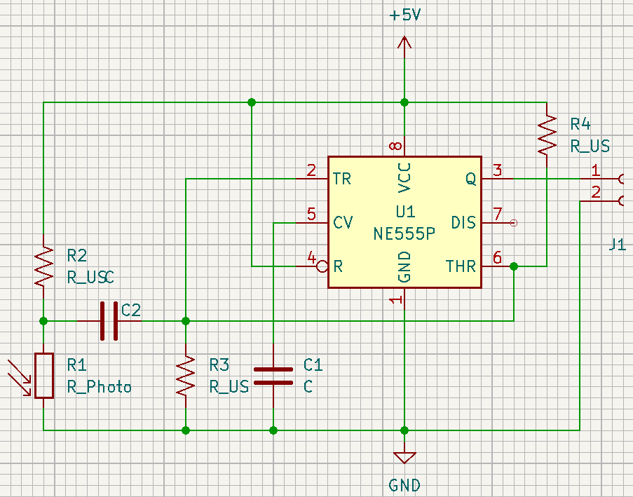
Can I get members insight into using a 555 timer as a schmidt-trigger design that I pulled from the Internet?

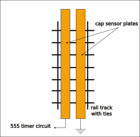
I found this schmidt-trigger design using a 555 timer. I would like to use it to condition the output of a photo-resistor. The 555 timer output will feed the input to a Arduino Mega. I'm in the process of bench testing the setup to finalize component values. While testing I figured I would throw it out to some more enlightened minds than mine for feedback.

I'm using the 555 only because I have a stock of them. I don't have any readily available smidth-trigger IC's so I figured I would go with what I have and build from scratch. Building from scratch especially using Internet designs comes with risk. I was hoping to mitigate the risk by getting community feedback.

If inquiring minds suggest you don't want to do this, that is a good thing.

  • Sign in to reply
  • Cancel

Top Replies

  • AE7HD
    AE7HD over 2 years ago in reply to colporteur +1
    I have a fair amount of experience with 555 timers, IR sensing, break beam circuits, etc. I'd like to help. But I need to know what you are trying to do. What is the ultimate goal?
  • colporteur
    colporteur over 2 years ago in reply to AE7HD +1
    Is this the sensor placement you are suggesting?
  • colporteur
    colporteur over 2 years ago in reply to Jan Cumps +1
    Sorry JC I have a reluctance to invest anymore effort in the IR solution. Modification of the train cars is something that frowned upon. This applied to even putting a magnet for another solution. I…
Parents
  • AE7HD
    0 AE7HD over 2 years ago

    So now that I know it is for model railroad sensing... have you considered capacitive sensing? The trains are metal, at least as far as the trucks, yes?

    • Cancel
    • Vote Up 0 Vote Down
    • Sign in to reply
    • Verify Answer
    • Cancel
  • colporteur
    0 colporteur over 2 years ago in reply to AE7HD

    I haven't looked at capacitive sensing. I did try hal-effect. The locomotive motor is not sensed by the transistor I have. Plan B place magnet on bottom of car. This works but if the train coast it leaves the sensor after triggering. It also requires modification to the cars by placing a magnet.

    I have also tried current sense. The Design Challenge gave me a sensor to test that worked. In a DC train powered system the track voltage can be reversed. The sensor doesn't like it.

    I have successfully used the IR sensor to create a scale speed testing device. It worked pretty good until I turned on the halogen light and then it went for a crap.

    • Cancel
    • Vote Up 0 Vote Down
    • Sign in to reply
    • Verify Answer
    • Cancel
  • Jan Cumps
    0 Jan Cumps over 2 years ago in reply to colporteur
    colporteur said:
    I have also tried current sense. The Design Challenge gave me a sensor to test that worked. In a DC train powered system the track voltage can be reversed. The sensor doesn't like it.

    can a rectifier fix that?

    • Cancel
    • Vote Up 0 Vote Down
    • Sign in to reply
    • Verify Answer
    • Cancel
  • AE7HD
    0 AE7HD over 2 years ago in reply to colporteur

    I've used this circuit for remote capacitive sensing. It returns a pulse width proportional to capacitance between the sensor plate and ground. It is described here as a level sensor, but it also works as a body sensor, touch sensor, basically anything conductive that gets close will cause the pulse width to get longer.

    https://hackaday.io/project/183506-remote-continuous-liquid-level-sensor-555-timer

    To use: connect to one pin of an Arduino. 

    Now just time how long it stays high between low pulses.

    The sensor should be two small copper plates or foil next to each other under the train, one connected to the sensor input, the other to circuit ground. Do NOT ground the sensor at the track, only back at the Arduino.

    You'll just have to test it and see how sensitive it is in your case. Larger copper plates will be more sensitive. Make both plates the same size.

    • Cancel
    • Vote Up 0 Vote Down
    • Sign in to reply
    • Verify Answer
    • Reject Answer
    • Cancel
  • colporteur
    0 colporteur over 2 years ago in reply to AE7HD

    image

    Is this the sensor placement you are suggesting?

    • Cancel
    • Vote Up +1 Vote Down
    • Sign in to reply
    • Verify Answer
    • Cancel
Reply
  • colporteur
    0 colporteur over 2 years ago in reply to AE7HD

    image

    Is this the sensor placement you are suggesting?

    • Cancel
    • Vote Up +1 Vote Down
    • Sign in to reply
    • Verify Answer
    • Cancel
Children
  • AE7HD
    0 AE7HD over 2 years ago in reply to colporteur

    That should work. Remember, though, don't ground it to the track. The 555 circuit can sit right under the copper pieces, so there is very little wire to add parasitic capacitance.

    • Cancel
    • Vote Up 0 Vote Down
    • Sign in to reply
    • Verify Answer
    • Reject Answer
    • Cancel
  • AE7HD
    0 AE7HD over 2 years ago in reply to colporteur

    You may have the ability to measure capacitance with your DMM. Usually the lowest range is in nF, but 0.001nF = 1pF. You can get a rough idea that way of how much change there is.

    Or build my device that uses two 555 timers to measure capacitance. It uses the display on your DMM, where on the lowest range, 1pF is 1mV. On the lowest scale, most DMMs can measure down to 0.1mV, so you can have 0.1pF fine grained measurements.

    https://hackaday.io/project/183405-dual-tlc555-capacitance-meter-01pf-resolution

    How accurate depends on the capacitor you use to calibrated it. Let's face it, 5% is fine for 99.999% of what we do, so a capacitor between 100 and 200pF is good to go, even if it is 5% or better tolerance. Lots of mica capacitors in that range are 2 or 3% tolerance.

    • Cancel
    • Vote Up 0 Vote Down
    • Sign in to reply
    • Verify Answer
    • Cancel
element14 Community

element14 is the first online community specifically for engineers. Connect with your peers and get expert answers to your questions.

  • Members
  • Learn
  • Technologies
  • Challenges & Projects
  • Products
  • Store
  • About Us
  • Feedback & Support
  • FAQs
  • Terms of Use
  • Privacy Policy
  • Legal and Copyright Notices
  • Sitemap
  • Cookies

An Avnet Company © 2025 Premier Farnell Limited. All Rights Reserved.

Premier Farnell Ltd, registered in England and Wales (no 00876412), registered office: Farnell House, Forge Lane, Leeds LS12 2NE.

ICP 备案号 10220084.

Follow element14

  • X
  • Facebook
  • linkedin
  • YouTube