element14 Community
element14 Community
    Register Log In
  • Site
  • Search
  • Log In Register
  • About Us
  • Community Hub
    Community Hub
    • What's New on element14
    • Feedback and Support
    • Benefits of Membership
    • Personal Blogs
    • Members Area
    • Achievement Levels
  • Learn
    Learn
    • Ask an Expert
    • eBooks
    • element14 presents
    • Learning Center
    • Tech Spotlight
    • STEM Academy
    • Webinars, Training and Events
    • Learning Groups
  • Technologies
    Technologies
    • 3D Printing
    • FPGA
    • Industrial Automation
    • Internet of Things
    • Power & Energy
    • Sensors
    • Technology Groups
  • Challenges & Projects
    Challenges & Projects
    • Design Challenges
    • element14 presents Projects
    • Project14
    • Arduino Projects
    • Raspberry Pi Projects
    • Project Groups
  • Products
    Products
    • Arduino
    • Avnet Boards Community
    • Dev Tools
    • Manufacturers
    • Multicomp Pro
    • Product Groups
    • Raspberry Pi
    • RoadTests & Reviews
  • Store
    Store
    • Visit Your Store
    • Choose another store...
      • Europe
      •  Austria (German)
      •  Belgium (Dutch, French)
      •  Bulgaria (Bulgarian)
      •  Czech Republic (Czech)
      •  Denmark (Danish)
      •  Estonia (Estonian)
      •  Finland (Finnish)
      •  France (French)
      •  Germany (German)
      •  Hungary (Hungarian)
      •  Ireland
      •  Israel
      •  Italy (Italian)
      •  Latvia (Latvian)
      •  
      •  Lithuania (Lithuanian)
      •  Netherlands (Dutch)
      •  Norway (Norwegian)
      •  Poland (Polish)
      •  Portugal (Portuguese)
      •  Romania (Romanian)
      •  Russia (Russian)
      •  Slovakia (Slovak)
      •  Slovenia (Slovenian)
      •  Spain (Spanish)
      •  Sweden (Swedish)
      •  Switzerland(German, French)
      •  Turkey (Turkish)
      •  United Kingdom
      • Asia Pacific
      •  Australia
      •  China
      •  Hong Kong
      •  India
      •  Korea (Korean)
      •  Malaysia
      •  New Zealand
      •  Philippines
      •  Singapore
      •  Taiwan
      •  Thailand (Thai)
      • Americas
      •  Brazil (Portuguese)
      •  Canada
      •  Mexico (Spanish)
      •  United States
      Can't find the country/region you're looking for? Visit our export site or find a local distributor.
  • Translate
  • Profile
  • Settings
555 Timers
  • Technologies
  • More
555 Timers
Forum Analysis of a 555 circuit design, will it work, maybe there is a better way
  • Blog
  • Forum
  • Documents
  • Polls
  • Files
  • Members
  • Mentions
  • Sub-Groups
  • Tags
  • More
  • Cancel
  • New
Join 555 Timers to participate - click to join for free!
Actions
  • Share
  • More
  • Cancel
Forum Thread Details
  • State Not Answered
  • Replies 24 replies
  • Subscribers 47 subscribers
  • Views 2053 views
  • Users 0 members are here
  • 555 timer
  • circuit design
Related

Analysis of a 555 circuit design, will it work, maybe there is a better way

colporteur
colporteur 11 months ago

I'm looking to build an End of Train (EOT) circuit. The model railroad folks I hang out with, just purchased a commercial unit. After gagging at the price, I figured why not build one.

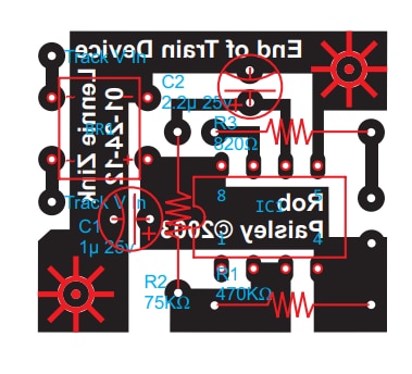
My search found this resource https://techlib.com/area_50/Readers/Lennie/End%20of%20Train-1.pdf complete with PCB. Unfortunately all the links are dead so I had to generate a schematic from the PCB layout.

image

Question: Will the circuit work? Are there any reasons for the design?

Instead of bread boarding the design I figured the folks that hang out here are great and offering solutions. Tapping into the experience of the members surely helps. Nothing like experience to find a solution fast.

image

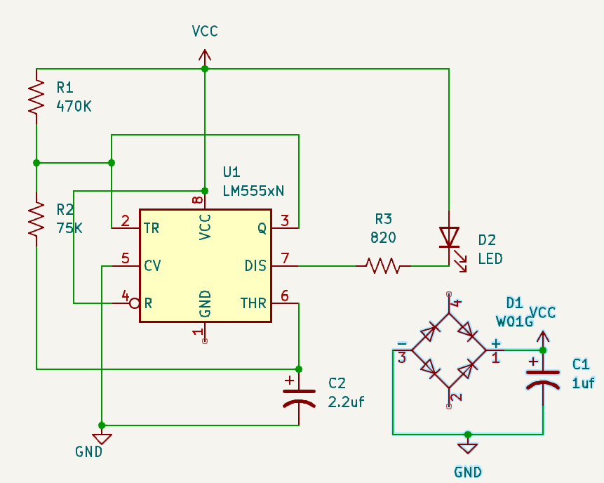
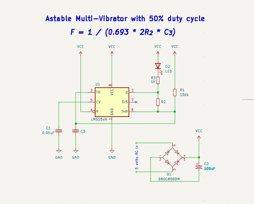
I have some concerns with the circuit. I couldn't found a 555 circuit that uses pin 7 as an output. I took a look through Cabe Force Essential 555 IC book (Cabe hangs out here:) and found nothing like this beast.

I'm not sure of the design. It looks like nothing I have found.

I'm thinking it would have been easier to just start from scratch. 

  • Sign in to reply
  • Cancel

Top Replies

  • scottiebabe
    scottiebabe 11 months ago +3
    Perhaps pin 1 is here?
  • beacon_dave
    beacon_dave 11 months ago +3
    colporteur said: Unfortunately all the links are dead so I had to generate a schematic from the PCB layout. Flashing Rear-End Device For DCC Systems https://web.archive.org/web/20140926093814/http…
  • dougw
    dougw 11 months ago +2
    What flashing rate do you need? You can buy LEDs that automatically flash:  PRO SIGNAL PSG91916 If you need other rates you could try: https://evandesigns.com/products/flashing-leds-for-hobbies…
Parents
  • aswinvenu
    0 aswinvenu 11 months ago

    I think what you are looking for is an astable multivibrator.

    image

    • Cancel
    • Vote Up +2 Vote Down
    • Sign in to reply
    • Verify Answer
    • Cancel
  • colporteur
    0 colporteur 11 months ago in reply to aswinvenu

    I believe the design I was hoping to use was riddled with errors.  scottiebabe pointed out the chip position error and your drawing suggests a number of other errors. Pins 6 & 7 are connected to together on the PCB and there is no capacitor on Pin 5. your drawing also increases the filter cap.

    I have seen designs were there are caps on pin 5 and some where there are none. What is best practice?

    In your frequency formula there is a constant (0.693). I've seen constants in formulas before. I can't recall if they are the same. Where does this constant value come from.

    • Cancel
    • Vote Up 0 Vote Down
    • Sign in to reply
    • Verify Answer
    • Cancel
Reply
  • colporteur
    0 colporteur 11 months ago in reply to aswinvenu

    I believe the design I was hoping to use was riddled with errors.  scottiebabe pointed out the chip position error and your drawing suggests a number of other errors. Pins 6 & 7 are connected to together on the PCB and there is no capacitor on Pin 5. your drawing also increases the filter cap.

    I have seen designs were there are caps on pin 5 and some where there are none. What is best practice?

    In your frequency formula there is a constant (0.693). I've seen constants in formulas before. I can't recall if they are the same. Where does this constant value come from.

    • Cancel
    • Vote Up 0 Vote Down
    • Sign in to reply
    • Verify Answer
    • Cancel
Children
  • jc2048
    0 jc2048 11 months ago in reply to colporteur

    The constant is ln(2).

    The 2 comes from the relationship between the switching thresholds. When charging, the lower threshold is twice as far away from VCC as the upper threshold. When discharging, the upper threshold is twice as far away from 0V as the lower one. The natural log is involved because the charging curve is exponential in shape.

    If you want to delve down further, and work it out from first principles, you'll need to read up about RC time constants, and more generally about circuit analysis.

    • Cancel
    • Vote Up +1 Vote Down
    • Sign in to reply
    • Verify Answer
    • Cancel
  • aswinvenu
    0 aswinvenu 11 months ago in reply to colporteur

    Pin 5 is the Control Voltage (CV). Internally this voltage is generated using a voltage divider. Adding a capacitor will help to produce more a stable control voltage. Good practice is definitely to use the cap.
    The design I shared use the same Resistor R2 for both charging and discharging the Cap C3. If you search for astable multivibrator using NE555 you can find design using two resistor solutions as well.

    • Cancel
    • Vote Up 0 Vote Down
    • Sign in to reply
    • Verify Answer
    • Cancel
element14 Community

element14 is the first online community specifically for engineers. Connect with your peers and get expert answers to your questions.

  • Members
  • Learn
  • Technologies
  • Challenges & Projects
  • Products
  • Store
  • About Us
  • Feedback & Support
  • FAQs
  • Terms of Use
  • Privacy Policy
  • Legal and Copyright Notices
  • Sitemap
  • Cookies

An Avnet Company © 2025 Premier Farnell Limited. All Rights Reserved.

Premier Farnell Ltd, registered in England and Wales (no 00876412), registered office: Farnell House, Forge Lane, Leeds LS12 2NE.

ICP 备案号 10220084.

Follow element14

  • X
  • Facebook
  • linkedin
  • YouTube