element14 Community
element14 Community
    Register Log In
  • Site
  • Search
  • Log In Register
  • Community Hub
    Community Hub
    • What's New on element14
    • Feedback and Support
    • Benefits of Membership
    • Personal Blogs
    • Members Area
    • Achievement Levels
  • Learn
    Learn
    • Ask an Expert
    • eBooks
    • element14 presents
    • Learning Center
    • Tech Spotlight
    • STEM Academy
    • Webinars, Training and Events
    • Learning Groups
  • Technologies
    Technologies
    • 3D Printing
    • FPGA
    • Industrial Automation
    • Internet of Things
    • Power & Energy
    • Sensors
    • Technology Groups
  • Challenges & Projects
    Challenges & Projects
    • Design Challenges
    • element14 presents Projects
    • Project14
    • Arduino Projects
    • Raspberry Pi Projects
    • Project Groups
  • Products
    Products
    • Arduino
    • Avnet Boards Community
    • Dev Tools
    • Manufacturers
    • Multicomp Pro
    • Product Groups
    • Raspberry Pi
    • RoadTests & Reviews
  • About Us
  • Store
    Store
    • Visit Your Store
    • Choose another store...
      • Europe
      •  Austria (German)
      •  Belgium (Dutch, French)
      •  Bulgaria (Bulgarian)
      •  Czech Republic (Czech)
      •  Denmark (Danish)
      •  Estonia (Estonian)
      •  Finland (Finnish)
      •  France (French)
      •  Germany (German)
      •  Hungary (Hungarian)
      •  Ireland
      •  Israel
      •  Italy (Italian)
      •  Latvia (Latvian)
      •  
      •  Lithuania (Lithuanian)
      •  Netherlands (Dutch)
      •  Norway (Norwegian)
      •  Poland (Polish)
      •  Portugal (Portuguese)
      •  Romania (Romanian)
      •  Russia (Russian)
      •  Slovakia (Slovak)
      •  Slovenia (Slovenian)
      •  Spain (Spanish)
      •  Sweden (Swedish)
      •  Switzerland(German, French)
      •  Turkey (Turkish)
      •  United Kingdom
      • Asia Pacific
      •  Australia
      •  China
      •  Hong Kong
      •  India
      •  Korea (Korean)
      •  Malaysia
      •  New Zealand
      •  Philippines
      •  Singapore
      •  Taiwan
      •  Thailand (Thai)
      • Americas
      •  Brazil (Portuguese)
      •  Canada
      •  Mexico (Spanish)
      •  United States
      Can't find the country/region you're looking for? Visit our export site or find a local distributor.
  • Translate
  • Profile
  • Settings
Connector Technology & Design
  • Technologies
  • More
Connector Technology & Design
Blog Easy Technical Connector Illustrations for Documentation, using 3D CAD!
  • Blog
  • Forum
  • Documents
  • Quiz
  • Events
  • Polls
  • Files
  • Members
  • Mentions
  • Sub-Groups
  • Tags
  • More
  • Cancel
  • New
Join Connector Technology & Design to participate - click to join for free!
  • Share
  • More
  • Cancel
Group Actions
  • Group RSS
  • More
  • Cancel
Engagement
  • Author Author: shabaz
  • Date Created: 25 Oct 2025 3:53 PM Date Created
  • Views 114 views
  • Likes 11 likes
  • Comments 12 comments
  • freecad
  • documentation
  • kicad
  • connector documentation
  • illustration
  • technical illustration
Related
Recommended

Easy Technical Connector Illustrations for Documentation, using 3D CAD!

shabaz
shabaz
25 Oct 2025

Table of Contents

  • Introduction
  • Obtain the 3D Model
  • Import into FreeCAD
  • TechDraw WorkBench
  • Export to SVG
  • Clean Up the Illustration
  • Import into KiCad
  • Summary


Introduction

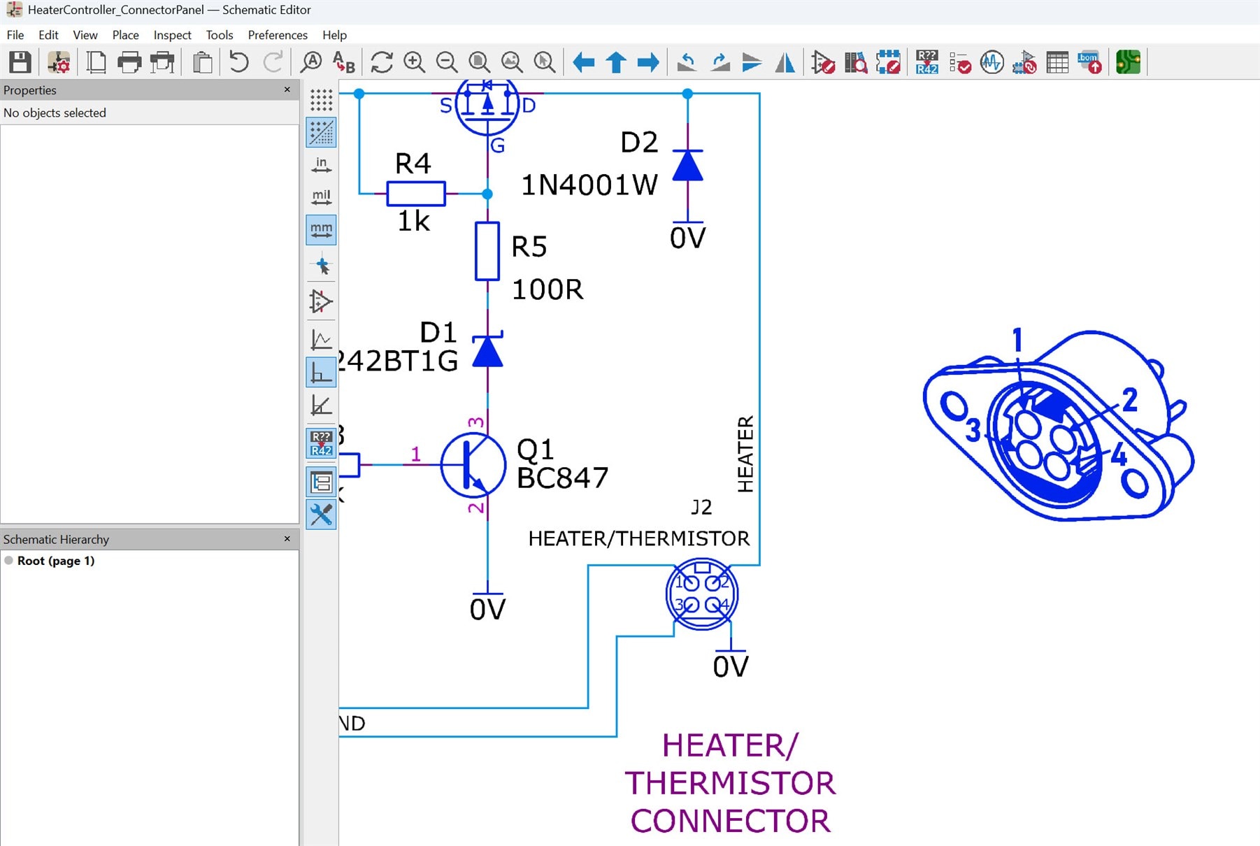
I always find it annoying figuring out connector pinouts, and so I sometimes place an illustration of the connector directly into documentation. However, sometimes it is hard to find a decent illustration!

image

This very short blog post describes a method I recently tried using, which relies on the availability of a 3D CAD file for the part in question.

In brief, the process involves viewing the 3D CAD model using FreeCAD, orienting it to the desired view, then displaying it in black-and-white outline form, and saving it as a vector format (SVG) that can be easily edited using InkScape.

Obtain the 3D Model

A lot of manufacturers nowadays offer 3D files in formats such as STEP, directly from their websites. Otherwise, there are third-party library sites that could be searched. The STEP format is useful because it can be directly imported into PCB CAD software such as KiCAD, or general-purpose 3D CAD software such as FreeCAD, too.

Import into FreeCAD

Launch FreeCAD, click File->New if needed, and then click File->Import, and load up that STEP file! Move the 3D object around with your mouse until it is oriented as you desire for your technical illustration.

TechDraw WorkBench

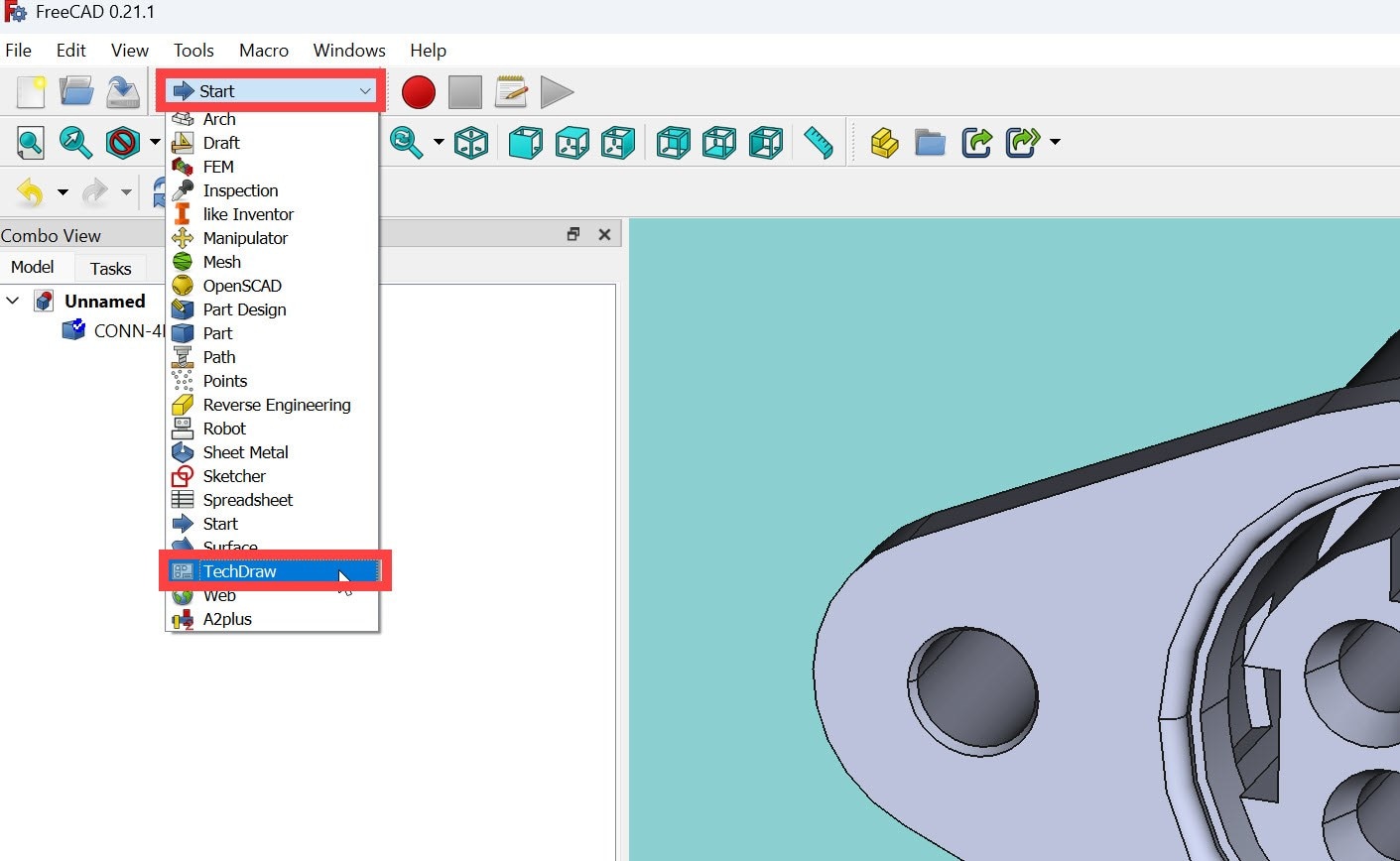
FreeCAD uses the concept of WorkBenches, which are essentially sets of tools for different tasks. Near the top of the FreeCAD window, you can click on a Start drop-down and change to the TechDraw workbench.

image

The aim is to create a technical illustration page, and place the 3D model onto it. To do that, click on TechDraw->Page->Insert Default Page (or Insert Page using Template and then select any template, such as A4 or Letter paper. A blank page will appear.

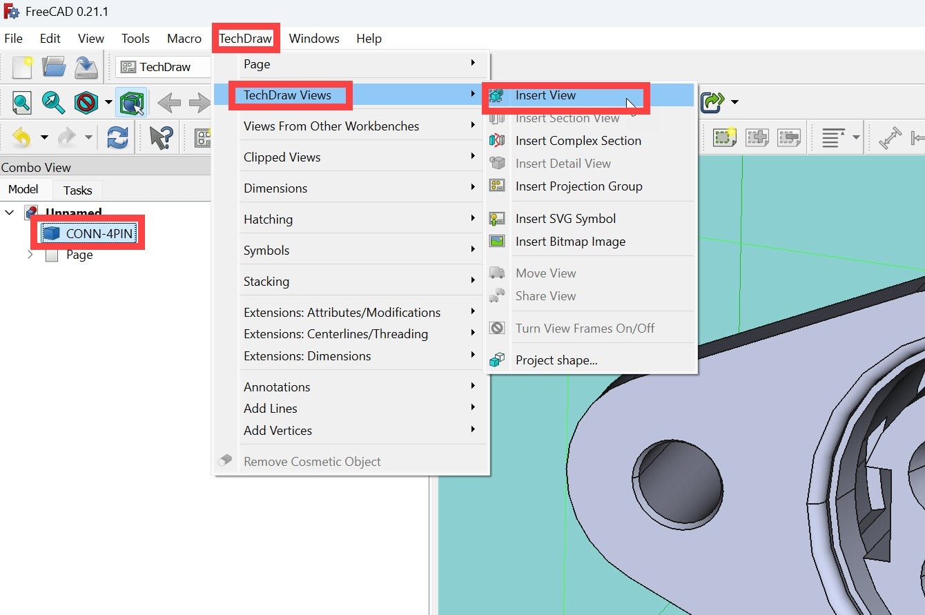
On the left side, you’ll see the Page object appear in the tree view. Above it is your 3D model name. Click on the 3D model name once to select it, then go to TechDraw->TechDraw Views->Insert View.

image

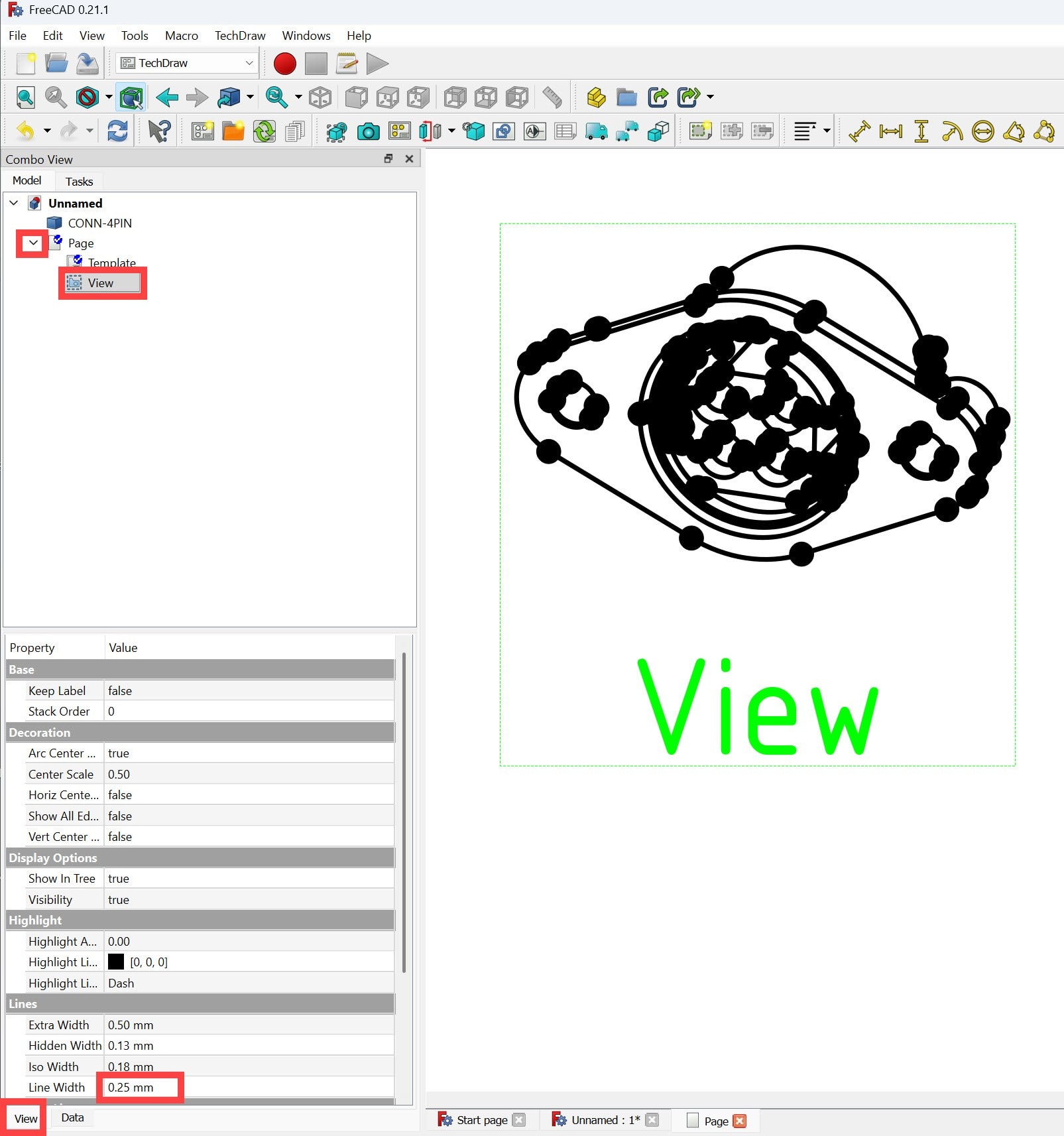
Next, expand the Page in the tree view, then select View in the expansion as shown in the screenshot below. You’ll see a black-and-white illustration appear in the main window, although it might be small and you’ll need to zoom in. The lines may have round blobs on the ends. If the lines look too thick, then on the left side, in the Property list, click on View at the bottom, and then modify the Line Width property to (say) 0.1 mm. You’ll still see round blobs, possibly, but that will be automatically resolved in the next steps.

image

Export to SVG

With the Page selected in the tree on the left, click on File->Export, then for the file type, choose Technical Drawing (*.svg *.dxf *.pdf) and save with a .svg suffix.

Clean Up the Illustration

Launch Inkscape software, create a new document, and then go to File->Import and load in the SVG file. It might appear small, so zoom in. Any round blobs have hopefully disappeared.

With the SVG illustration selected (you could just type Ctrl-A to select all), click on Object->Ungroup

Note that if your illustration has a technical drawing border around it, you can select it and delete it at this stage if desired.

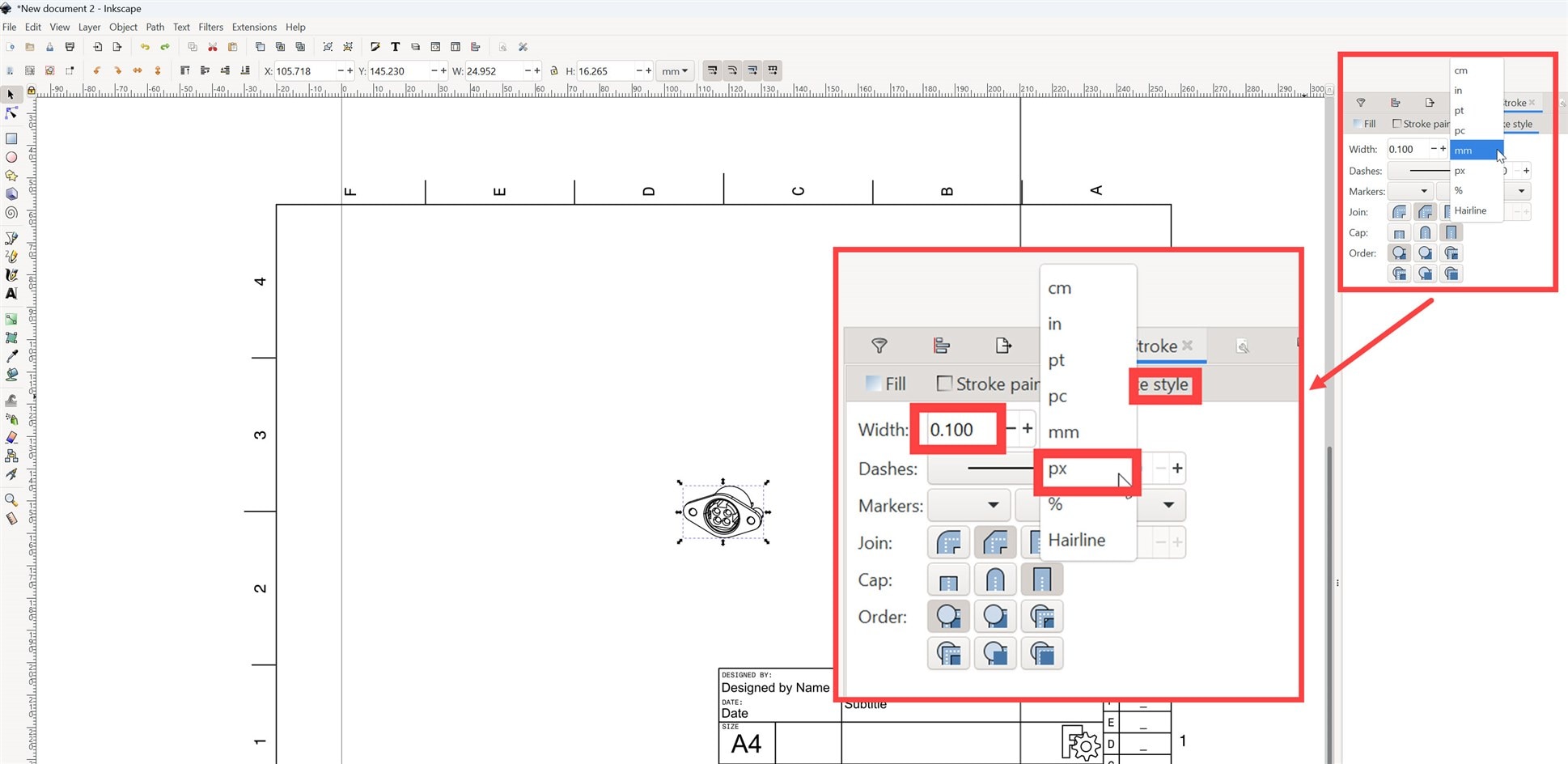
Click on Object->Fill and Stroke and select the Stroke Style tab in the pane on the right. Now you can change the line width as desired (it’s easier by doing it using px rather than percentage, and trying fractional values like 1.2 or whatever.

image

The chances are, the illustration has more detail than desired. You could select all and go to Object->Ungroup again, to ungroup a bit more, and then select unnecessary lines and delete them.

Once you’re happy, save the illustration in PNG format (I simply did a print-screen, rather than use FreeCAD for that) and then add any annotations using whatever editor you’re comfortable with (I used PowerPoint, and then did print-screen again to save to the final desired PNG file).

Import into KiCad

The PNG file can be used directly in documents such as Word files. If you wish to insert the image into the source schematic file, then that can be done using KiCad’s Image Converter program from the KiCad Control Panel.

Launch the Image Converter, go to File->Open and select the PNG file. On the right side of the Image Converter, select the desired image size, then choose the Output Format to be Symbol, and then click Export to File, and choose an appropriate name.

Next, open up KiCad’s Symbol Editor, and choose a user library, and then right-click on the library name and choose Import Symbol. Locate the file, name your symbol, save the result, and you’re done; it can now be added as a symbol into any schematic.

image

Summary

FreeCAD’s TechDraw workbench allows for easy representation of 3D CAD models in a black-and-white outline. It’s possible to export as an SVG file that can be cleaned up and simplified for illustration purposes using InkScape, and then inserted into any desired document, such as Word files or KiCad schematics.

Although the example here uses a connector model, the procedure isn't specific to connectors, and similar steps could be used for any 3D model.

Thanks for reading!

  • Sign in to reply

Top Comments

  • shabaz
    shabaz 1 day ago +1
    Another example, this time importing two STEP files during the "Import into FreeCAD" part of the process (and then right-clicking on one of them in the tree view, and selecting Transform, which makes some…
  • colporteur
    colporteur 21 hours ago in reply to shabaz

    Inkscape, GIMP and scribus are three of my graphic/publishing companions.

    • Cancel
    • Vote Up 0 Vote Down
    • Sign in to reply
    • More
    • Cancel
  • beacon_dave
    beacon_dave 1 day ago in reply to shabaz

    Perhaps needs some 'googly eyes' on the subwoofers to make it look more friendly. Slight smile

    The ceiling construction reminds me of one those wooden burr puzzles that used to be popular at Xmas time. One wrong move and the whole ceiling comes down. Although the vertical pegs are actually solid aluminium bars and not wood.

    • Cancel
    • Vote Up 0 Vote Down
    • Sign in to reply
    • More
    • Cancel
  • shabaz
    shabaz 1 day ago in reply to dougw

    Great! I really like the fact that since the process starts with 3D, one can take a lot of care to precisely orient for best pinout clarity before converting to a 2D graphic file. 

    • Cancel
    • Vote Up 0 Vote Down
    • Sign in to reply
    • More
    • Cancel
  • shabaz
    shabaz 1 day ago in reply to colporteur

    I cannot imagine an engineering life without at least KiCad and FreeCAD now! And just a few years ago, I had tried neither. Makes me wonder what other software tools I'm missing out on.

    • Cancel
    • Vote Up 0 Vote Down
    • Sign in to reply
    • More
    • Cancel
  • shabaz
    shabaz 1 day ago in reply to beacon_dave

    Hehe I see a two-headed evil overlord! Nice lecture hall/theatre.. 

    • Cancel
    • Vote Up 0 Vote Down
    • Sign in to reply
    • More
    • Cancel
>
element14 Community

element14 is the first online community specifically for engineers. Connect with your peers and get expert answers to your questions.

  • Members
  • Learn
  • Technologies
  • Challenges & Projects
  • Products
  • Store
  • About Us
  • Feedback & Support
  • FAQs
  • Terms of Use
  • Privacy Policy
  • Legal and Copyright Notices
  • Sitemap
  • Cookies

An Avnet Company © 2025 Premier Farnell Limited. All Rights Reserved.

Premier Farnell Ltd, registered in England and Wales (no 00876412), registered office: Farnell House, Forge Lane, Leeds LS12 2NE.

ICP 备案号 10220084.

Follow element14

  • X
  • Facebook
  • linkedin
  • YouTube