element14 Community
element14 Community
    Register Log In
  • Site
  • Search
  • Log In Register
  • Community Hub
    Community Hub
    • What's New on element14
    • Feedback and Support
    • Benefits of Membership
    • Personal Blogs
    • Members Area
    • Achievement Levels
  • Learn
    Learn
    • Ask an Expert
    • eBooks
    • element14 presents
    • Learning Center
    • Tech Spotlight
    • STEM Academy
    • Webinars, Training and Events
    • Learning Groups
  • Technologies
    Technologies
    • 3D Printing
    • FPGA
    • Industrial Automation
    • Internet of Things
    • Power & Energy
    • Sensors
    • Technology Groups
  • Challenges & Projects
    Challenges & Projects
    • Design Challenges
    • element14 presents Projects
    • Project14
    • Arduino Projects
    • Raspberry Pi Projects
    • Project Groups
  • Products
    Products
    • Arduino
    • Avnet Boards Community
    • Dev Tools
    • Manufacturers
    • Multicomp Pro
    • Product Groups
    • Raspberry Pi
    • RoadTests & Reviews
  • Store
    Store
    • Visit Your Store
    • Choose another store...
      • Europe
      •  Austria (German)
      •  Belgium (Dutch, French)
      •  Bulgaria (Bulgarian)
      •  Czech Republic (Czech)
      •  Denmark (Danish)
      •  Estonia (Estonian)
      •  Finland (Finnish)
      •  France (French)
      •  Germany (German)
      •  Hungary (Hungarian)
      •  Ireland
      •  Israel
      •  Italy (Italian)
      •  Latvia (Latvian)
      •  
      •  Lithuania (Lithuanian)
      •  Netherlands (Dutch)
      •  Norway (Norwegian)
      •  Poland (Polish)
      •  Portugal (Portuguese)
      •  Romania (Romanian)
      •  Russia (Russian)
      •  Slovakia (Slovak)
      •  Slovenia (Slovenian)
      •  Spain (Spanish)
      •  Sweden (Swedish)
      •  Switzerland(German, French)
      •  Turkey (Turkish)
      •  United Kingdom
      • Asia Pacific
      •  Australia
      •  China
      •  Hong Kong
      •  India
      •  Korea (Korean)
      •  Malaysia
      •  New Zealand
      •  Philippines
      •  Singapore
      •  Taiwan
      •  Thailand (Thai)
      • Americas
      •  Brazil (Portuguese)
      •  Canada
      •  Mexico (Spanish)
      •  United States
      Can't find the country/region you're looking for? Visit our export site or find a local distributor.
  • Translate
  • Profile
  • Settings
Embedded and Microcontrollers
  • Technologies
  • More
Embedded and Microcontrollers
Blog Debug / JTAG Probe - XDS110: UART and Utility GPIO
  • Blog
  • Forum
  • Documents
  • Quiz
  • Polls
  • Files
  • Members
  • Mentions
  • Sub-Groups
  • Tags
  • More
  • Cancel
  • New
Join Embedded and Microcontrollers to participate - click to join for free!
  • Share
  • More
  • Cancel
Group Actions
  • Group RSS
  • More
  • Cancel
Engagement
  • Author Author: Jan Cumps
  • Date Created: 31 Aug 2019 1:58 PM Date Created
  • Views 2569 views
  • Likes 5 likes
  • Comments 1 comment
  • xds110
  • debug
  • jtag
  • arm
  • code_composer_studio
Related
Recommended

Debug / JTAG Probe - XDS110: UART and Utility GPIO

Jan Cumps
Jan Cumps
31 Aug 2019

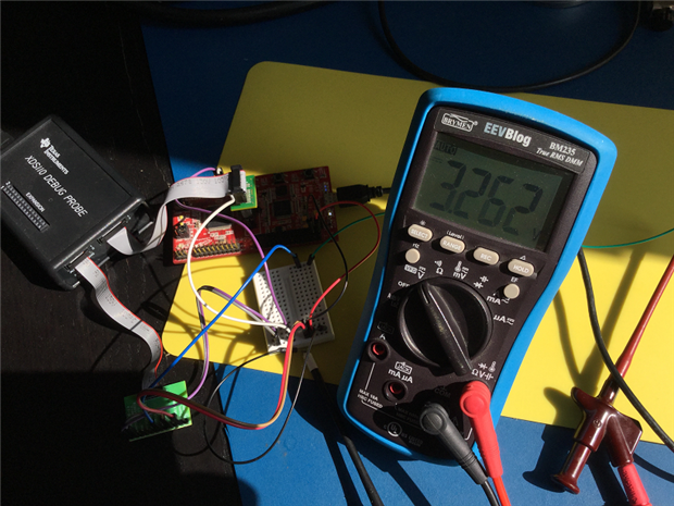
I bought my first hardware debugger. The TI XDS110 Debug Probe.

In this second post I'm checking the UART interface and the GPIO pins. Two functions that can help to automate the testing of our designs.

image


When you're building a commercial product*, being able to automatically verify each unit can bring good value.

Placing the device in a test jig and have it programmed and tested automatically can improve efficiency and quality.

The XDS110 debug probe has some support for that.

It can

  • program your device,
  • script execution (where you can set and modify conditions, validate and report state at a particular source line, etc ...),
  • interact with on-board UART (at the logic level),
  • can deliver power to your device < 400 mA and
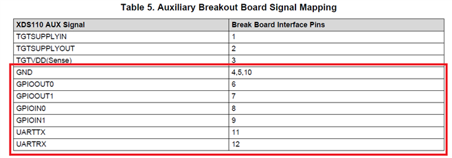
  • has 2 input and output pins that you can use in the automation.


image

In situations where testing your design doesn't need a full setup with data acquisition and oscilloscope, this can be a valuable setup.


Several of these functions are available out of the box when you have an evaluation kit. The value of the debugger materialises when you are designing solutions with embedded controllers.

You typically don't provide on-board hardware debug capabilities but JTAG test points.

The debugger uses that connector to program and test the device.


UART


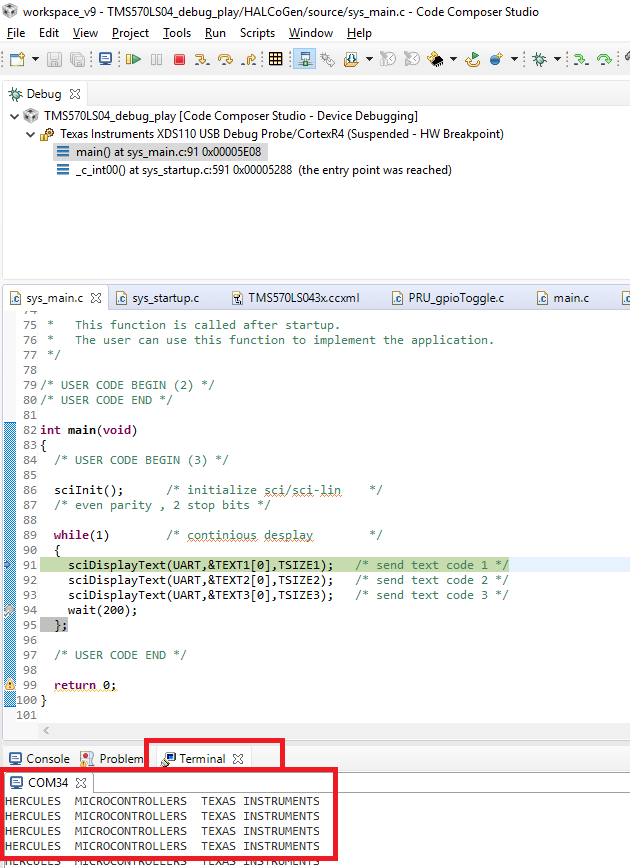
This is a fairly standard function when you work with an evaluation kit. Most manufacturers provide debug and UART support over USB.

In a test situation, also when your design does not need serial communication, you can use this to exchange data between the harware and the debugger.

You can embed debug specific UART commands in the firmware that aren't part of production firmware that help the automation.

You first load the debug firmware and run test cases that rely on that feature.

Then you load the production firmware and run the tests that don't need this interaction.


For designs that have serial communication as a production feature, you can use the debugger to test that.

The debugger's TX connects to the controllers RX and vice versa.


image


GPIO


The XDS110 has 2 input and two output pins that you can use in your test setup.

The core intent of these pins is to control boot modes of the unit under test.

However, they are plain inputs and outputs, so you can use them in any way you want during the test process.

The output pins can be used to trigger an activity or simulate inputs. The inputs can validate logic levels.


CCS comes with a command line utility called dbgjtag that can set and read the pins.


To drive the debugger's output pins 0 or 1 (both low, pin 1 high, pin 2 high, 1 and 2 high):


ccs\ccs_base\common\uscif>dbgjtag -f @xds110 -Y gpiopins, config=0x3, write=0x0
ccs\ccs_base\common\uscif>dbgjtag -f @xds110 -Y gpiopins, config=0x3, write=0x1
ccs\ccs_base\common\uscif>dbgjtag -f @xds110 -Y gpiopins, config=0x3, write=0x2
ccs\ccs_base\common\uscif>dbgjtag -f @xds110 -Y gpiopins, config=0x3, write=0x3


On the input side, the command line does not mask.


ccs\ccs_base\common\uscif>dbgjtag -f @xds110 -Y gpiopins, read=yes


Our two input pins are the two lowest bits of a LSB 4 bit port.

If both are high the utility returns: 0x0f. (0b1111)

If input pin 0 is low, the return value is 0x0b. (0b1011)

If 1 is low, 0x0 (0b0111)

Both low gives 0x03 (0011).


You can use a scripting language or a workflow environment such as LabVIEW to integrate these 4 GPIOs in your test set.

When you need more (8) inputs or outputs, have a look at this project: SCPI on a Raspberry Pi: LabVIEW Driver for LAB Switch.


* automating the product validation is also useful when you're designing a single prototype. It's a good way to validate that you did not break functionality after changing hardware or firmware.

If you design a test environment, you don't have to repeat manual testing ad infinitum. You become sloppy at that after a while anyways.


Related blog
New Debug / JTAG Probe - XDS110: First Steps
Debug / JTAG Probe - XDS110: UART and Utility GPIO
  • Sign in to reply
  • DAB
    DAB over 5 years ago

    Good post Jan.


    DAB

    • Cancel
    • Vote Up 0 Vote Down
    • Sign in to reply
    • More
    • Cancel
element14 Community

element14 is the first online community specifically for engineers. Connect with your peers and get expert answers to your questions.

  • Members
  • Learn
  • Technologies
  • Challenges & Projects
  • Products
  • Store
  • About Us
  • Feedback & Support
  • FAQs
  • Terms of Use
  • Privacy Policy
  • Legal and Copyright Notices
  • Sitemap
  • Cookies

An Avnet Company © 2025 Premier Farnell Limited. All Rights Reserved.

Premier Farnell Ltd, registered in England and Wales (no 00876412), registered office: Farnell House, Forge Lane, Leeds LS12 2NE.

ICP 备案号 10220084.

Follow element14

  • X
  • Facebook
  • linkedin
  • YouTube