element14 Community
element14 Community
    Register Log In
  • Site
  • Search
  • Log In Register
  • Community Hub
    Community Hub
    • What's New on element14
    • Feedback and Support
    • Benefits of Membership
    • Personal Blogs
    • Members Area
    • Achievement Levels
  • Learn
    Learn
    • Ask an Expert
    • eBooks
    • element14 presents
    • Learning Center
    • Tech Spotlight
    • STEM Academy
    • Webinars, Training and Events
    • Learning Groups
  • Technologies
    Technologies
    • 3D Printing
    • FPGA
    • Industrial Automation
    • Internet of Things
    • Power & Energy
    • Sensors
    • Technology Groups
  • Challenges & Projects
    Challenges & Projects
    • Design Challenges
    • element14 presents Projects
    • Project14
    • Arduino Projects
    • Raspberry Pi Projects
    • Project Groups
  • Products
    Products
    • Arduino
    • Avnet Boards Community
    • Dev Tools
    • Manufacturers
    • Multicomp Pro
    • Product Groups
    • Raspberry Pi
    • RoadTests & Reviews
  • Store
    Store
    • Visit Your Store
    • Choose another store...
      • Europe
      •  Austria (German)
      •  Belgium (Dutch, French)
      •  Bulgaria (Bulgarian)
      •  Czech Republic (Czech)
      •  Denmark (Danish)
      •  Estonia (Estonian)
      •  Finland (Finnish)
      •  France (French)
      •  Germany (German)
      •  Hungary (Hungarian)
      •  Ireland
      •  Israel
      •  Italy (Italian)
      •  Latvia (Latvian)
      •  
      •  Lithuania (Lithuanian)
      •  Netherlands (Dutch)
      •  Norway (Norwegian)
      •  Poland (Polish)
      •  Portugal (Portuguese)
      •  Romania (Romanian)
      •  Russia (Russian)
      •  Slovakia (Slovak)
      •  Slovenia (Slovenian)
      •  Spain (Spanish)
      •  Sweden (Swedish)
      •  Switzerland(German, French)
      •  Turkey (Turkish)
      •  United Kingdom
      • Asia Pacific
      •  Australia
      •  China
      •  Hong Kong
      •  India
      •  Korea (Korean)
      •  Malaysia
      •  New Zealand
      •  Philippines
      •  Singapore
      •  Taiwan
      •  Thailand (Thai)
      • Americas
      •  Brazil (Portuguese)
      •  Canada
      •  Mexico (Spanish)
      •  United States
      Can't find the country/region you're looking for? Visit our export site or find a local distributor.
  • Translate
  • Profile
  • Settings
Embedded and Microcontrollers
  • Technologies
  • More
Embedded and Microcontrollers
Blog New Debug / JTAG Probe - XDS110: First Steps
  • Blog
  • Forum
  • Documents
  • Quiz
  • Polls
  • Files
  • Members
  • Mentions
  • Sub-Groups
  • Tags
  • More
  • Cancel
  • New
Join Embedded and Microcontrollers to participate - click to join for free!
  • Share
  • More
  • Cancel
Group Actions
  • Group RSS
  • More
  • Cancel
Engagement
  • Author Author: Jan Cumps
  • Date Created: 9 Jul 2019 4:26 PM Date Created
  • Views 10987 views
  • Likes 9 likes
  • Comments 16 comments
  • xds110
  • debug
  • jtag
  • arm
  • code_composer_studio
Related
Recommended

New Debug / JTAG Probe - XDS110: First Steps

Jan Cumps
Jan Cumps
9 Jul 2019

I bought my first hardware debugger. The TI XDS110 Debug Probe.

Up till now, I always used the on-board debug modules of development boards to program and debug devices. That's great for prototyping and evaluation. In industry settings, you use different tools to do development on custom boards and to program + test designs on a production line.

image


Most development and evaluation boards have a debugger on board.

It's often a dedicated IC that uses USB to handle power, serial communication and debugging at once:

  • Many TI LaunchPads use a TM4C microcontroller (they run XDS110 emulation, same as the probe I'm describing here).
  • Older LaunchPads use the FTDI FT2322 in combination with a Xilinx XC2C32A CoolRunner-II CPLD (XDS100 emulation).
  • The Infineon XMC 2Go has an Infineon XMC4200 (Segger emulation).
  • The Maxim MAX32660 dev board uses a MAX32625 (Segger emulation).


The principle is always the same: provide an easy to use development and debug experience with just a single USB connection.

When you are evaluating a microcontroller - or learning to program it - this is perfect. The best possible experience.

Also in the prototype stage you often use an evaluation board instead of designing your own PCB with microcontroller on it.

The on-board debugger gives you a headstart then.


Once you go beyond this point and you build for production, the situation changes.

You can still get by for early prototypes of your device. Several dev boards allow to tap off the debugger signal and use it to program other devices.

While working on your bench, you can use the original dev board's debugger and wire it up to your early proto's JTAG (and optionally serial RX/TX) lines.


In particular the SimpleLink CC1310 LaunchPad is handy. It has a dedicated 10 pin debug output  connector and most pins can be tapped of via the jumpers in the middle of the board.

image


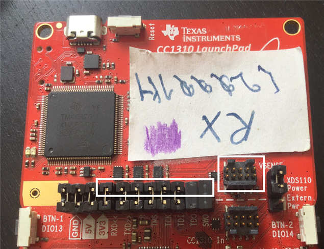
But these emulators don't have all debug pins - it's a subset. And it's not an officially supported debug/program device for production use.

Given these constraints, they are still excellent for home and early design.

For later stages of the development where you're no longer tinkering on your workbench, a separate debugger/ programmer will come into play.


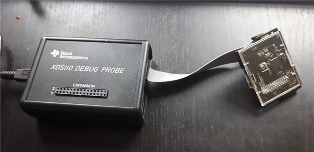
What's in the Package?


The debugger comes with a few add-ons. These allow you to adapt the pin-out of the probe (see TI Compact 20-pin in the table below) to a few popular configurations.


image

source: product page


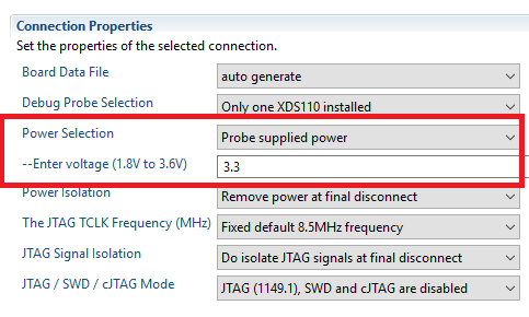
There's an auxiliary output with configurable I/O pins and a supply that can be used to power your target design.

These are the main parts:


  • debugger
  • TI 20-pin debug cable
    • TI 20-pin to TI 14-pin converter adapter
    • TI 20-pin to ARM Cortex 20-pin converter adapter
    • TI 20-pin to ARM Cortex 10-pin converter adapter
  • 14-pin auxiliary cable
    • Breakout board for auxiliary cable


The layout of the JTAG types supported by the device are shown below.

image

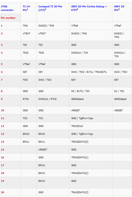
source: TI Resource Explorer


Column 2, 4 and 5 are supported by the 3 adapters. Column 3 is the pinout of the default flat cable.


Tests


I've tested the debugger with three different ARM microcontrollers.

The SimpleLink CC1310 shown above in the blog header.

A Hercules TMS570LS04 automotive device. This time I used the debug probe's aux to power the target design:

image


image

The third device was a CC2650 SensorTag.

image

In all situations, the debugger worked straight away.

I used Code Composer Studio to load firmware and run a full debug session with breakpoints, stepping, watches and expressions.

I also used the UniFlash loader to test a firmware load from command line and SmartRF Studio to talk to the on-board radio of the CC1310 and CC2650 devices.

The critique I have is that the status LEDs are almost invisible.

The LEDs shine straight-up from the PCB, but the holes to see them are at the side of the case. You almost have to lay your face on the table and peek through the holes to see activity.


Most development boards will have at least 2 USB ports when you plug them into a PC: the debug port and a UART serial port. This probe is the same. But the serial lines aren't automatically connected to the target controller. They aren't part of the JTAG standard.

The serial TX and RX lines are available on the aux connector. You can tap them of there and connect them to your microcontroller's UART peripheral.
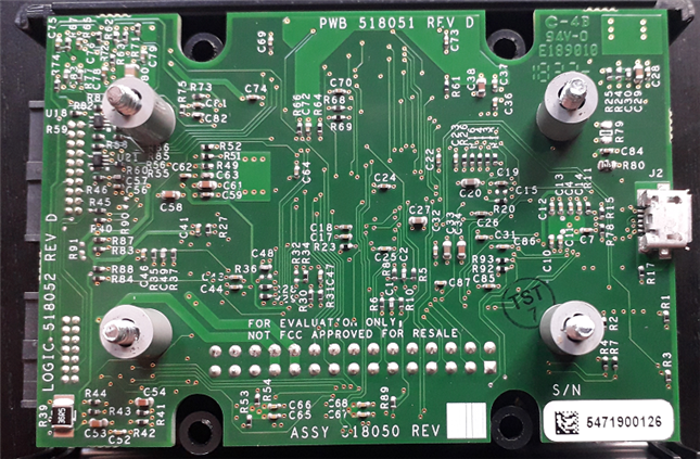
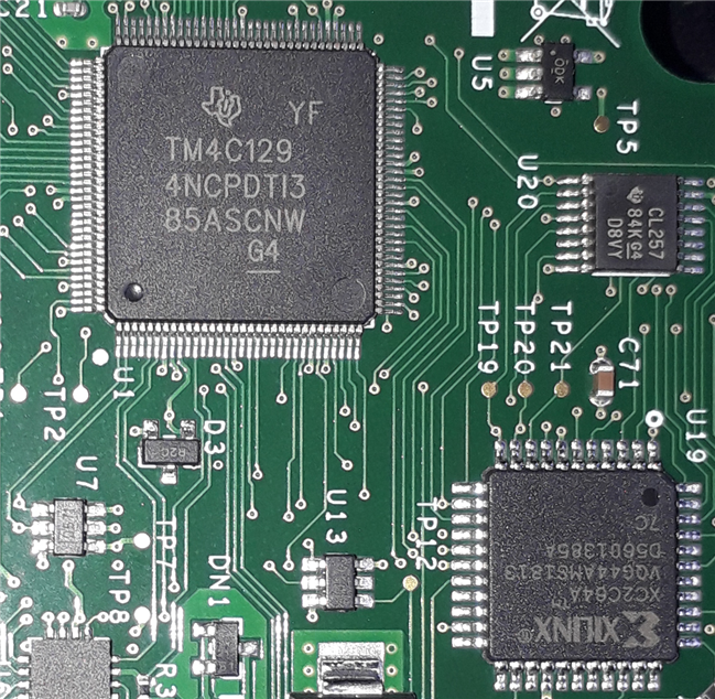


Inside


I've taken some pictures of the internals.

image

image


image


Related blog
New Debug / JTAG Probe - XDS110: First Steps
Debug / JTAG Probe - XDS110: UART and Utility GPIO
  • Sign in to reply

Top Comments

  • Fred27
    Fred27 over 5 years ago in reply to Jan Cumps +5
    That is odd. Maybe the evaluation board passed with flying colours and the decided to churn them out without updating the silkscreen. "Nobody would open it up anyway." I'm not sure why but I'm surprised…
  • Jan Cumps
    Jan Cumps over 5 years ago in reply to genebren +4
    The one I have is a compromise. With its $99 price tag (without shipment) it's affordable for most companies. It's got decent feature coverage but is at the lower end for data transfer speed. On a production…
  • Jan Cumps
    Jan Cumps over 5 years ago +4
    This is strange on a not-for-evaluation product pcb
  • Fred27
    Fred27 over 4 years ago in reply to drac98

    drac98  wrote:

    I need to debug the Beaglebone Black (BBB) using debug. I got a TI Lanuchpad CC1310


    BBB has a cTI 20 pin.

    Launchpad's XDS out has a (ARM) 10 pin.


    Can I wire them up point to point by looking the pin layouts in here?

    Will it work or do I need an adapter or a breakout borad (I don't know the difference)?

    I remember trying to use a Launchpad's debugger by soldering a ribbon cable to the BBB, failing to get it working, and then buying an XDS110. I think the problem ended up being something else and the Launchpad should (in theory) have worked. I'm afraid I can't remember anything more than that though. It's certainly worth a try if you have the time to try it.

    • Cancel
    • Vote Up 0 Vote Down
    • Sign in to reply
    • More
    • Cancel
  • Jan Cumps
    Jan Cumps over 4 years ago in reply to drac98

    Maybe Fred27 knows. He made more progress than me: Debugging the BeagleBone PRU in CCS

    • Cancel
    • Vote Up +1 Vote Down
    • Sign in to reply
    • More
    • Cancel
  • drac98
    drac98 over 4 years ago in reply to Jan Cumps

    Yes, I need to debug the kernel to write and test some USB drivers.

    • Cancel
    • Vote Up 0 Vote Down
    • Sign in to reply
    • More
    • Cancel
  • Jan Cumps
    Jan Cumps over 4 years ago in reply to drac98

    I haven't tried with a BB. I have a BB Green, but jtag is not populated.

    Are you going to debug the kernel, or a user space program?

    For user programs, I use GDB server as a software debugger over tcp-ip.

    • Cancel
    • Vote Up 0 Vote Down
    • Sign in to reply
    • More
    • Cancel
  • drac98
    drac98 over 4 years ago

    Hi,

    I'm new to JTAG.

    I need to debug the Beaglebone Black (BBB) using debug. I got a TI Lanuchpad CC1310


    BBB has a cTI 20 pin.

    Launchpad's XDS out has a (ARM) 10 pin.


    Can I wire them up point to point by looking the pin layouts in here?

    Will it work or do I need an adapter or a breakout borad (I don't know the difference)?

    • Cancel
    • Vote Up 0 Vote Down
    • Sign in to reply
    • More
    • Cancel
>
element14 Community

element14 is the first online community specifically for engineers. Connect with your peers and get expert answers to your questions.

  • Members
  • Learn
  • Technologies
  • Challenges & Projects
  • Products
  • Store
  • About Us
  • Feedback & Support
  • FAQs
  • Terms of Use
  • Privacy Policy
  • Legal and Copyright Notices
  • Sitemap
  • Cookies

An Avnet Company © 2025 Premier Farnell Limited. All Rights Reserved.

Premier Farnell Ltd, registered in England and Wales (no 00876412), registered office: Farnell House, Forge Lane, Leeds LS12 2NE.

ICP 备案号 10220084.

Follow element14

  • X
  • Facebook
  • linkedin
  • YouTube