


Table of Contents
TLDR Section
The easyL1105 is a TI MSPM0L1105 Development Board that can be DIY'd. Here are the links:
For more blogs and information: Use the searchbox, tags are easyL1105 or MSPM0
easyL1105 GitHub repository page
Introduction
I was browsing the Texas Instruments (TI) website, and noticed they had some very low-cost, very basic ARM Cortex-M0+ microcontrollers. I was keen on finding something low-power, small (but hand-solderable), and cheap. I aim to eventually use such a chip for interfacing to simple sensors for a few possible projects (one requires some sort of low-accuracy current sensor, and another requires an presence sensor), so all I require is a basic built-in ADC, I2C, SPI, or perhaps UART, and either control an output, or send text to an I2C LCD display, or perhaps write to external SPI storage.
In the end, I decided to order a few parts from the TI MSPM0 L-Series, which they class as low-power, and I found a 28-pin variant which has a fair amount of general-purpose input/output (GPIO) connections.
The microcontroller doesn’t have any particularly remarkable features, other than the very low power consumption and cheapness, and the fact that it doesn’t require many components at all, not even a crystal oscillator. Just a few decoupling capacitors are all that’s technically required.
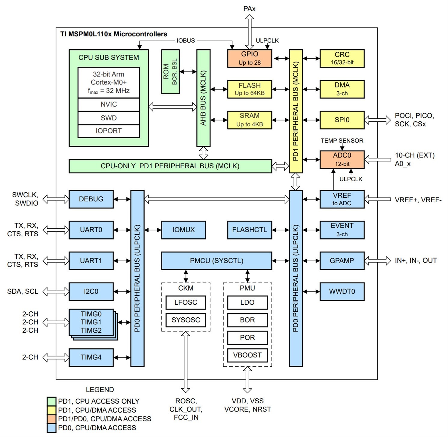
(Image source: Microcontroller PDF Datasheet)
In shutdown (with GPIO wakeup capability), current consumption is apparently 61 nA, which seems pretty low. RAM can be maintained and timers can be running in a ‘standby’ mode, where current consumption is 1uA, which also seems reasonable.
One more thing I really liked; it has an in-built bootloader that can accept firmware over the serial (UART) port, so that no separate programmer device is required for in-the-field updates. You could just attach it directly to a PC and program it up.
The particular part I went for is the L1105 (the full name is MSPM0L1105TDGS28R), which has 32 kByte of Flash memory and 4 kByte of RAM, but there is a pin-compatible L1106 upgrade part with 64 kByte of Flash if needed.
In terms of major downsides, there’s no ability to add a crystal oscillator if you need such precision. Interestingly, as a compromise, the chip can use an external 0.1% tolerance 100k resistor in order to create a reasonably precise internal oscillator, but it won’t compare with a crystal, of course. I would have liked an accurate RTC, but I suppose that could always be an external I2C peripheral chip, perhaps with a separate backup battery.
TI doesn’t actually have a dev-board for this particular L1105 part, but since it’s a simple chip, I’d much rather make my own dev-board, so I can get used to working with the chip without all the extras that many dev-boards have.
Circuit Description
The circuit is split up into three main sections, described next. For the PDF version of the schematic and the project files, see the easyL1105 project repository on GitHub.
1. Microcontroller Core
The core of the circuit is shown below (click to enlarge).
This doesn’t do much, other than breaking out most of the microcontroller connections to 0.1” pin headers. I took a reasonable guess at how the pins might be used, and so some are labelled with I2C and SPI connection names. A couple of pins are useful for timer-based input/output capabilities; for instance, one could use them for attaching a rotary encoder. As a simple user interface, the circuit has a single button (SW3) and a couple of LEDs attached to GPIO pins; it’s up to the user to write code to make use of that button and the LEDs.
There is a 5-pin header, J5, that can be used to attach a traditional SWD JTAG programmer device if required.
The BSL_RX and BSL_TX connections are used for uploading firmware via serial. To enable this, there is a BSL_BOOT button that needs to be held down during a reset. There are some non-populated resistor pads attached to the BSL_BOOT switch, because I’m unsure if that pin floats, or if the user may wish to permanently set that to a particular level.
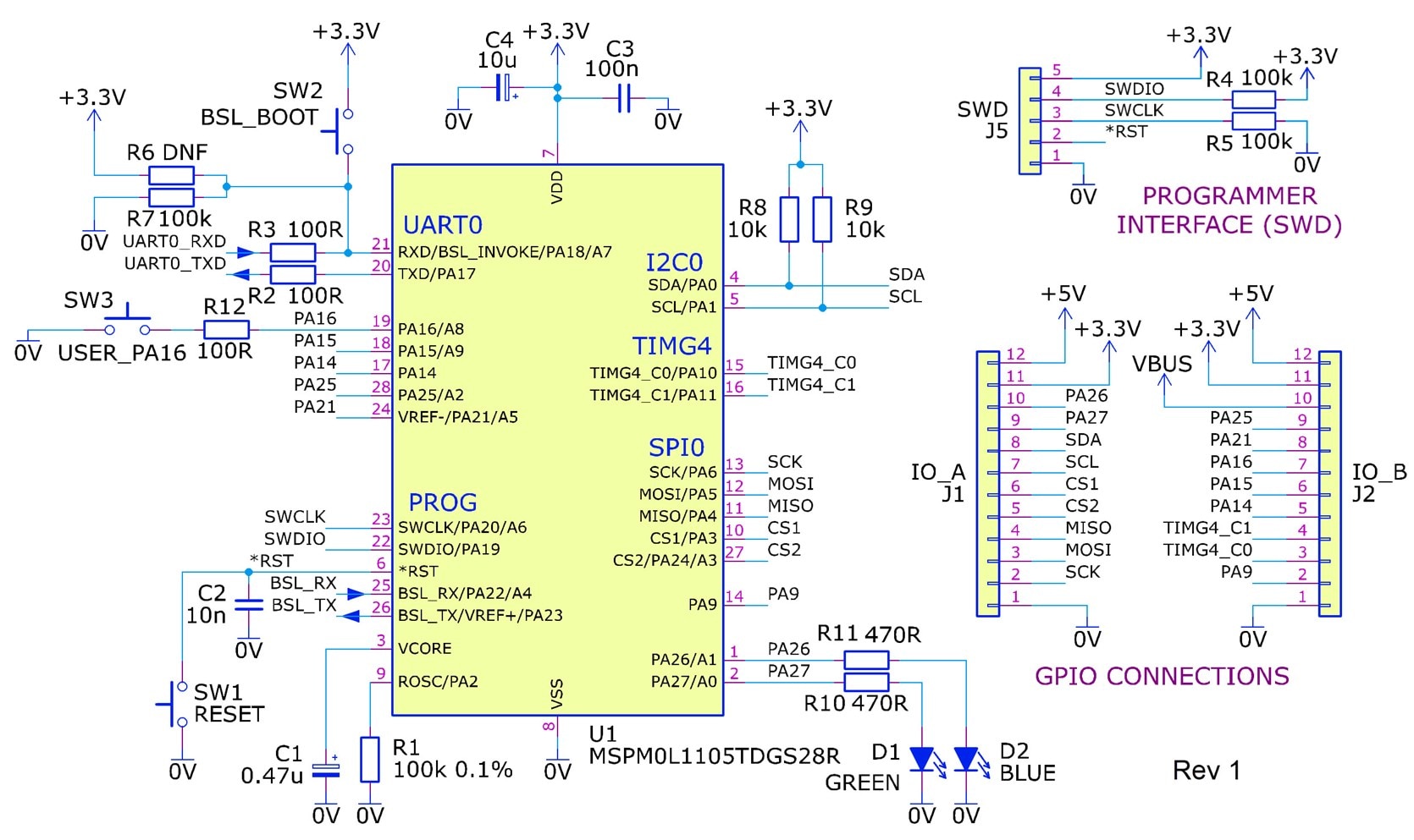
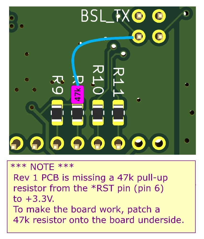
Note: It was later discovered that this Rev 1 circuit is missing a 47k pull-up resistor, from the *RST pin (pin 6 on the microcontroller) to +3.3V. It was easy to patch onto the underside of the PCB.
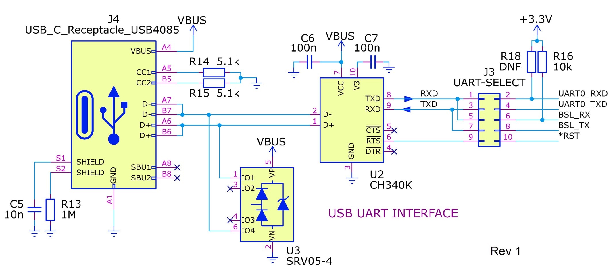
2. USB UART
Since I was keen to use the serial bootloader, the dev-board contains a USB-UART adapter. It’s based around a CH340K USB-UART chip, which I’ve never used before. The chip is a little unusual in that it uses pull-up resistors on the UART side if the chip is powered from 5V and not from the (lower) microcontroller voltage; that’s the reason for R16 on the right side of the circuit (R18 is not fitted, otherwise the microcontroller will always start in bootloader mode!). After some discussion with Jan Cumps it's likely R16 is not needed, so it could potentially be removed (depending on if the RX pin is floating or not on the microcontroller). The microcontroller reset pin is wired through a jumper on J3 to the RTS line, in case it is possible to automatically reset the board from the PC (if you're using the official TI app, UniFlash, then it's not possible, and the jumper needs to be removed). You would still need to manually press the BSL_BOOT button (although, if the microcontroller is new from the factory with the Flash erased, then for that first time the BSL_BOOT button doesn’t need to be pressed).
The pin headers labelled J3 are used with shorting jumpers to redirect the USB-UART from the BSL pins to alternative pins for UART0. This is so that the same USB-UART can be used for general program serial input/output, too.
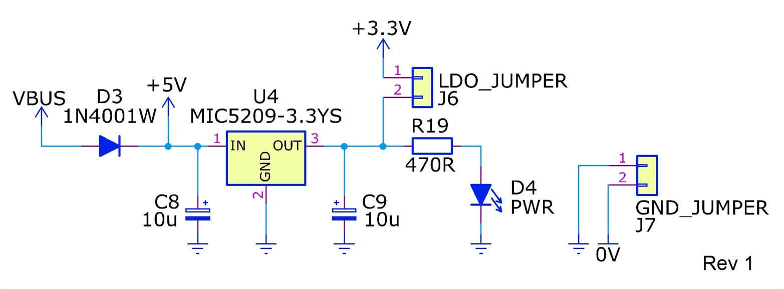
3. Voltage Regulator
The final bit of circuitry is a 3.3V regulator, which can be powered either by the USB connection or from a 5V labelled connection that is exposed on the GPIO pin headers. The two shorting jumpers can be used to separate the power to the microcontroller portion of the circuitry from the rest of the board. By removing the shorting jumpers, you could wire in a separate power supply if desired, or attach current measurement circuitry.
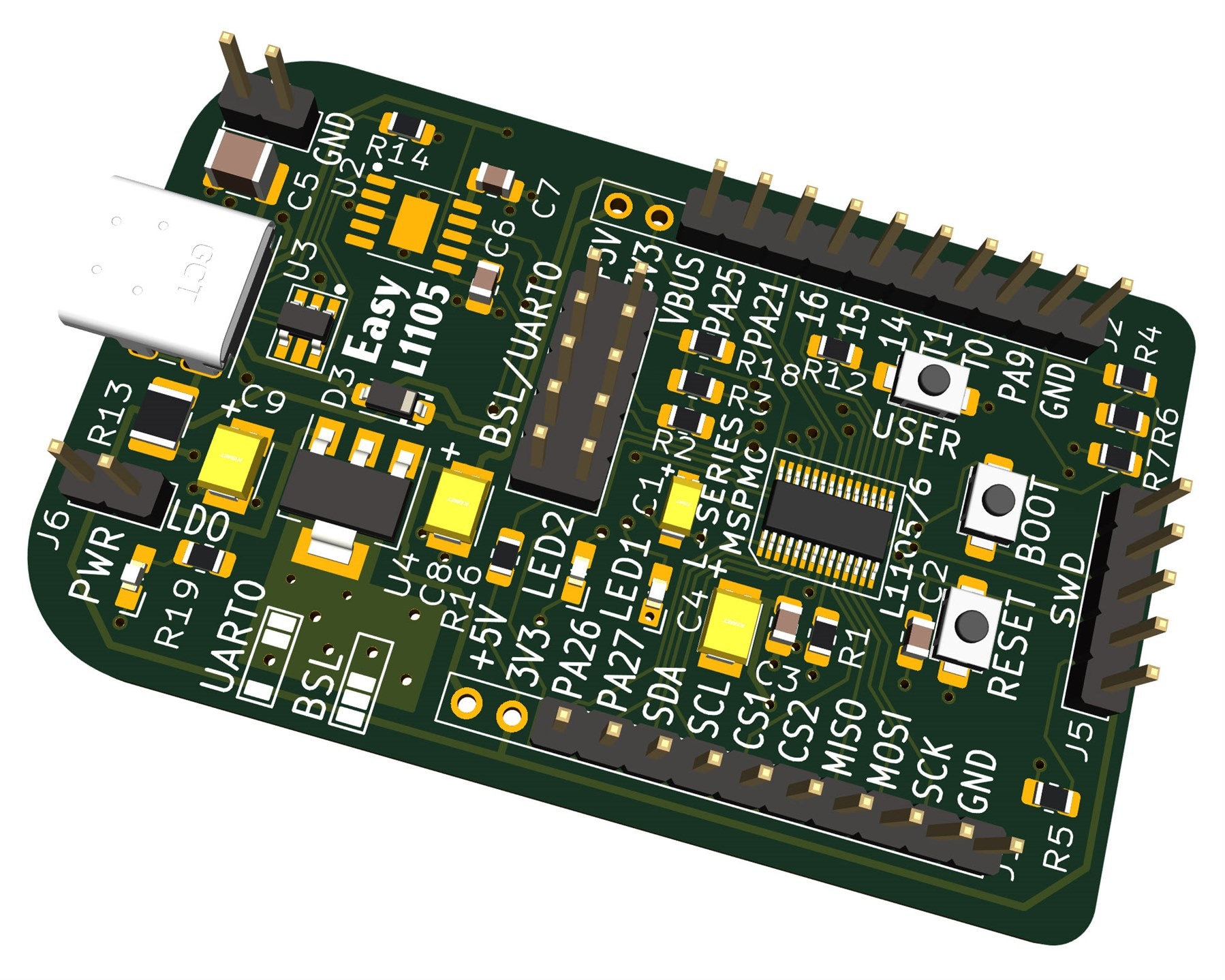
Circuit Board
An approximate render of the circuit board is shown below; it is about 60 x 40 mm.
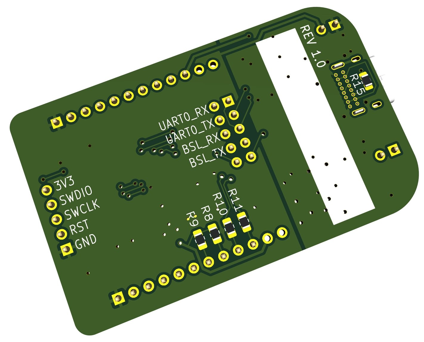
Underside:
Building and Running an Example Project
All the steps are described at the README file in the easyL1105 GitHub repository. Scroll down to the Example Project section to see the detail. By following the steps there, it is possible to build using either Keil or with GCC. The Keil steps were tested with Windows. GCC was tested with Windows and Linux.
The steps to use TI's UniFlash tool, for uploading the built .hex firmware file to the board, are also described at the same location.
Summary
TI’s MSPM0 L-series microcontrollers offer low-power and low-cost, and a simple development board was created for the 28-pin L1105 part (32 kByte Flash and 4 kByte RAM). The dev-board brings out most of the connections on the microcontroller, and also allows the testing of the serial bootloader capability of the chip, so that it can be programmed in the field, by connecting to a PC without any programmer hardware required.
The KiCad files and PCB files for sending to any PCB manufacturer are in the EasyL1105 GitHub repository. Although the board has not been tested yet (Edit: it has now been assembled and tried out. See the comments below for information about how to use the board). If you give it a go, it would be interesting to hear any feedback.
Also, if you have any ideas/uses for such a board or a similar one, it would be great to hear about them.
Thanks for reading.
Top Comments