


Table of Contents
Blog List
Introduction to Components in ESP-IDF
In the previous blogs I have talked purely about peripheral such as UART, I2C and ADC using ESP-IDF environment. This blog is more about how to create a component in ESP-IDF environment.
Components are software modules that provide specific functionality. They are portable to different projects within ESP-IDF environment. For example, there are Components for WiFi, Peripherals, Networking and those can be used with different projects in ESP-IDF and different versions. The good thing about this is that it makes code and libraries reusable in different projects and you can manage the projects quite well.
Creating components in ESP-IDF
There are different ways to create components. But the easiest way is using command idf.py create-component. This command will create a component structure and add it into a separate folder called components.
idf.py create-component "nameofcomponent"
The above command will create a component and add the required folder structure and files for the component.
I am creating a component for I2C Light intensity sensor. This sensor can measure the Lux level of the light with upto 20-bit resolution.
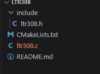
Adding source files inside the component
Next thing is to add the source files and add code for I2C operations. The full component code can be downloaded from my github. ESP-IDF suggests to create a common code for creating I2C devices using the following function. This function will create the device for us with required parameters.
There is also a function to delete the device to free the resources.
i2c_master_dev_handle_t ltr308_device_create(i2c_master_bus_handle_t bus_handle,
    const uint16_t dev_addr, const uint32_t dev_speed)
{
    i2c_device_config_t dev_cfg = {
        .dev_addr_length = I2C_ADDR_BIT_LEN_7,
        .device_address = dev_addr,
        .scl_speed_hz = dev_speed,
    };
    i2c_master_dev_handle_t dev_handle;
    // Add device to the I2C bus
    ESP_ERROR_CHECK(i2c_master_bus_add_device(bus_handle, &dev_cfg, &dev_handle));
    return dev_handle;
}

esp_err_t ltr308_device_delete(i2c_master_dev_handle_t dev_handle)
{
    return i2c_master_bus_rm_device(dev_handle);
}
After adding code to create and delete the devices, one can add code to read from/ write into the I2C device. The following code is to that. With this code one can now read or write the I2C device.
I have added more functions to set the sensor into right mode and set different parameters. After that one can read the light intensity values. The datasheet mentions the formula to get the Lux values from raw sensor data.
/**
* @brief Read the register value from the LTR308 sensor
* @param dev_handle The I2C device handle
* @param reg The register address to read
* @param data The buffer to store the read data
* @param len The length of the data to read
* @return ESP_OK on success, or an error code on failure
*/
static esp_err_t ltr308_read(i2c_master_dev_handle_t dev_handle, uint8_t reg, uint8_t *data, size_t len)
{
esp_err_t ret;
ret = i2c_master_transmit_receive(dev_handle, ®, 1, data, len, -1);
if (ret != ESP_OK) {
printf("Error reading from device: %d\n", ret);
return ret;
}
return ret;
}
/**
* @brief Write the register value to the LTR308 sensor
* @param dev_handle The I2C device handle
* @param reg The register address to write
* @param data The buffer containing the data to write
* @param len The length of the data to write
* @return ESP_OK on success, or an error code on failure
*/
static esp_err_t ltr308_write(i2c_master_dev_handle_t dev_handle, uint8_t reg, uint8_t *data, size_t len)
{
esp_err_t ret;
uint8_t buf[len + 1];
buf[0] = reg;
for (int i = 0; i < len; i++) {
buf[i + 1] = data[i];
}
ret = i2c_master_transmit(dev_handle, buf, sizeof(buf), -1);
if (ret != ESP_OK) {
printf("Error writing to device: %d\n", ret);
return ret;
}
return ret;
}
Using Components in existing project
After the component is created and all the files are added you can now add the component into your project files. For that simple thing is to add component inside main/idf_component.yml file.
Here is an example to add the component in the file. The version: "*" specifies that it can be any version found on the path mentioned with path: directive.
dependencies:
  ltr308:
    version: "*"
    path: esp\v6.0.2\esp-idf\examples\component_esp_ai\components\ltr308
Make sure to change the CMakeLists.txt file to add the REQUIRES sensor_driver_i2c line to add I2C related API functions during compilation process. You will also need to add the header file for I2C.
#include "driver/i2c_master.h"
#include "ltr308.h"
Now that we have added the component related values inside project files, we can modify main.c file to add lines to get the sensor data.
Inside the app_main() function you can add the following lines to get the sensor data values. After you compile and flash the project to the device you can get the sensor values.
esp_err_t ret = nvs_flash_init();

    i2c_master_bus_config_t i2c_mst_config = {
        .clk_source = I2C_CLK_SRC_DEFAULT,
        .i2c_port = -1,
        .scl_io_num = 9,
        .sda_io_num = 8,
        .glitch_ignore_cnt = 7,
        .flags.enable_internal_pullup = true,
     };

    i2c_master_bus_handle_t bus_handle;
    i2c_new_master_bus(&i2c_mst_config, &bus_handle);

    i2c_device_config_t dev_cfg = {
        .dev_addr_length = I2C_ADDR_BIT_LEN_7,
        .device_address = 0x53,
        .scl_speed_hz = 400000,
    };

    i2c_master_dev_handle_t dev_handle;
    i2c_master_bus_add_device(bus_handle, &dev_cfg, &dev_handle);
    dev_handle = ltr308_device_create(bus_handle, LTR308_I2C_ADDR, 400000);

    ltr308_enable(dev_handle);
    ltr308_set_gain(dev_handle, gain_3x);
    ltr308_set_resolution(dev_handle, e20_bit_400ms);
    ltr308_set_rate(dev_handle, eRate_500ms);

    float lux;

    while (1) {
        lux = ltr308_read_lux(dev_handle);

        printf(" Lux: %.2f\n", lux);
        vTaskDelay(2000 / portTICK_PERIOD_MS);
        gpio_set_level(IR_LED_GPIO, level);
    }

References
- ESP-IDF documentation
- ESP32-S3 AI Camera Module: Edge AI & Night Vision | DFRobot Wiki has the sensor mentioned here
- Sensor datasheet