


Table of Contents
Introduction
Presence sensing is something that was traditionally done using passive infra-red (PIR) sensors. Unlike PIR sensors, microwave sensors do not rely on thermal detection, nor do they rely on movement; in fact microwave sensors can distinguish between static and moving objects, and the objects can be cold or hot.
At home I have old microwave-based sensors as part of an alarm system, that essentially emit radio waves at a high frequency (multi-GHz), and they mix (using a cavity known as a waveguide, and a non-linear device) the received signal (reflected off objects, including humans) with the transmitted frequency, to generate a low-frequency signal that changes whenever there is any motion. Such older sensors are very sensitive, but they have disadvantages, primarily cost, and large size.
Nowadays, things have changed for the better! There are single-chip microwave devices that do it all! The antenna is now simply a trace on the PCB, rather than a large metal waveguide. The entire sensor can be extremely small and can be hidden behind panels in walls or ceilings, for instance. As a result, they are very unintrusive, and yet can provide deep insight into how an environment is being used. Unlike PIR sensors, microwave devices can detect stationary and moving objects, and can distinguish between them, and can even detect an approximate range.
There are many such devices from different manufacturers, and I have no idea which ones are effective and which are not! In the past, I tried one device, and it performed fine, however, I could not configure it, because I could not get hold of the chip documentation. I decided to try again with more devices, this time from a manufacturer called HLK. I wouldn’t say my quest for good documentation was entirely successful, but I’m happy with the information I’ve managed to glean/reverse-engineer so far.
This blog post documents what I’ve learned so far, about a HLK sensor series called HLK-LD2410, or LD2410 for short.
What is it? What can and can’t it do?
The LD2410 is a very small board, 35 x 7 mm, containing a microwave integrated circuit from a manufacturer I don’t recognize. There’s not a lot of detail about the chip or the board; they are mostly a black box, unfortunately. In principle, the device will transmit RF energy at microwave frequencies, and measure the energy bounced back, much like RADAR. As a result, the system can detect the presence of static or moving objects, and provide a report indicating the object type (static or moving), and a (very basic, ballpark) measurement of how near it is.
The device cannot provide an object count, nor can it indicate if the object is human, although the latter can sometimes be inferred if there is movement in a known deployed location. An object count could be achieved by deploying multiple sensors to cover different portions of a larger area, or by positioning sensors near an entrance or exit perhaps, but that is not a strength of this sensor; there are better options for that, such as thermal imaging sensors!

Exploring the Board
According to the board datasheet, the chip operates transmitting RF between the range of 24.0 to 24.25 GHz. The other side of the board contains a microcontroller from a manufacturer called ZhuHai Jieli.
The main negative is the current consumption; like many devices, it’s inefficient in generating microwave energy, and the average consumption is 80 mA at 5V (the board can accept 5-12V). As a result, battery operation is only feasible if the device is powered on intermittently. Wired operation is awkward for retrofitting in walls and ceilings.
At least two versions of the board are available from AliExpress, and they look almost identical. The LD2410B version of the board can be remotely monitored and configured using BLE. I don’t think it is worth it, because it requires enabling non-Google-app-store software installation on your phone. Besides, I don’t think people would want the possibility of unauthorized misconfiguration to occur in homes! Both versions of the board can also be configured via a serial (UART) interface, which I’ll discuss in this blog post.
The microcontroller has a different part code for the BLE version.

One version has a BLE antenna of course.

There is a 5-way pin header on one end of the board. The pin header has 1.27mm pitch, which is not easy to work with but is manageable.

Just the power supply pins and the OUT pin are required for simple usage of the board. The OUT pin will go high (3.3V) whenever the sensor has detected the presence of objects. I connected a resistor and LED to it for testing.
It is possible to get reports (in a basic and in a detailed form) from the serial UART interface which operates at 256 kbps. It is also possible to configure the device using that interface. The configuration is non-volatile, so it is feasible to configure the device and then just use the OUT pin if desired. However, for best insight into what’s been detected, the UART interface should be used for the reports.
Connecting the Board
There is a low-cost carrier board that merely contains a USB UART, and a socket to plug on the LD2410 module. I think it’s worth obtaining so that boards can be easily configured with it.

However, that board is not essential. Any 3.3V USB-UART adapter can be used. A popular 1.27 mm ready-made cable known as an “ARM SWD Cable” can be used to make the connections temporarily. The photo below shows my quick test setup.

If you’re using the carrier board, you may need to install a USB-Serial driver on the PC.
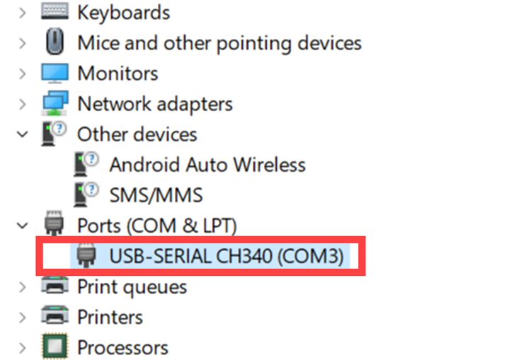
The driver can be found on the CH341 driver page here.
Download and unzip CH341SER.ZIP and then plug in the device, and go to Device Manager and update the driver for the unknown USB Serial device that will appear there.
Running the supplied PC Application
There is a ready-made PC application that can be used to monitor the device or to configure it. The tool is not bad, and fairly easy to self-figure out how to use it.
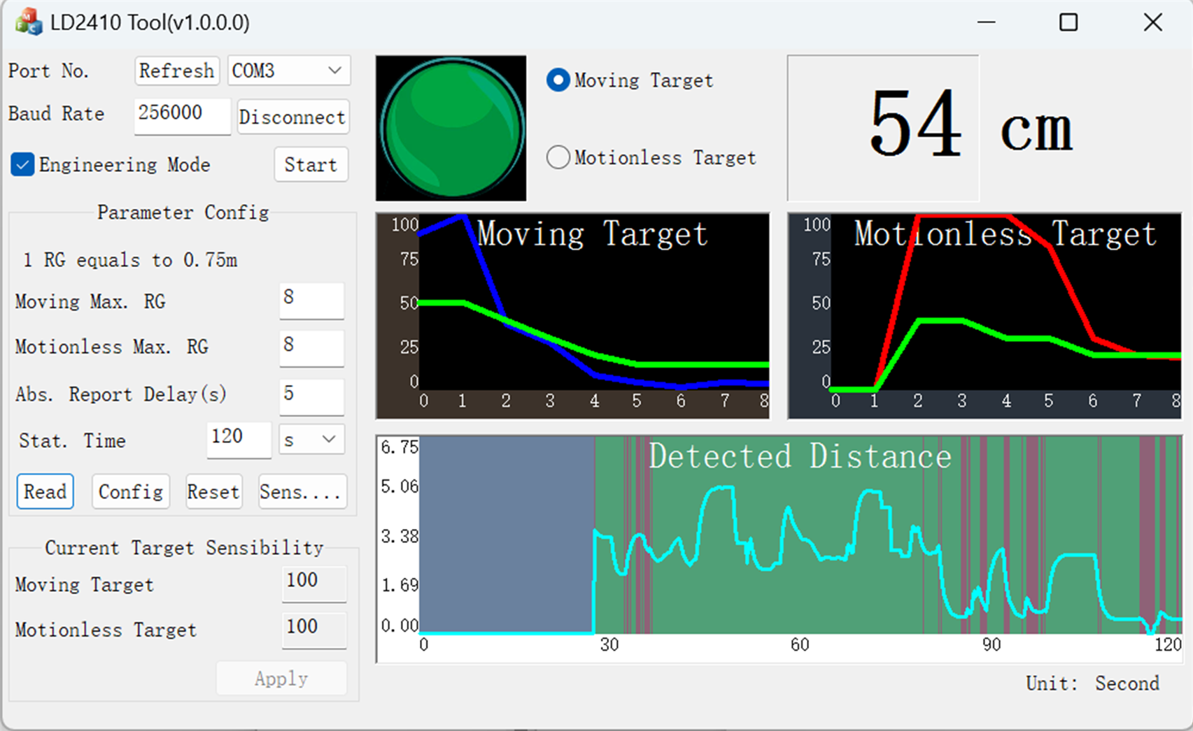
You’ll see a new window pop up by clicking on the Sensitivity button. The screenshot below shows its default settings. The RG values are ranges, in steps of about 75 cm. The two Sensitivity values for each range refer to a threshold that needs to be crossed for activity to be detected. The range is 0-100. The lower the number, the lower the threshold for detection. In other words, for maximum sensitivity, set the values to zero. If you don’t want the device to detect objects at a certain distance, then set the values to 100 for the corresponding range. For instance, if you only want to sense object presence extremely close to the sensor, then set all values to 100 in the table, except for the first row.

Understanding Reports
When the board is powered up, it immediately begins sending basic reports over the 256kbps UART connection. Each report is 23 bytes long.
The reports from the device are available in a Basic mode (23 bytes), and an Engineering mode (45 bytes); there is a checkbox in the app to select the mode. The PC application doesn’t provide the raw data, but it is available over the UART connection.
The Basic mode provides the following data:
- State
- Moving Distance
- Moving Energy
- Stationary Distance
- Stationary Energy
- Detection Distance
I don’t entirely understand these parameters, but this is my interpretation of them:
State: The state is one of four values.
no_target: Nothing static or moving detected
moving_target: Movement detected
stationary_target: No movement detected, but there is something near the sensor.
combined_target: There is something near the sensor, and it is moving
moving energy: This is like a confidence level, depending on speed on movement I think! 100 is very confident, and 0 is not very confident. This value is only useful when the state is moving_target or combined_target.
stationary_energy: This is a confidence level between 0 and 100 (100 being very confident). This value is only useful when the state is stationary_target or combined_target
moving_distance: This is the distance in centimeters from the moving target
stationary_distance: This is the distance in centimeters from the stationary target
detection_distance: I don’t know what this value represents. In any case, I don’t think it is important, because the other parameters provide a lot of useful information anyway.
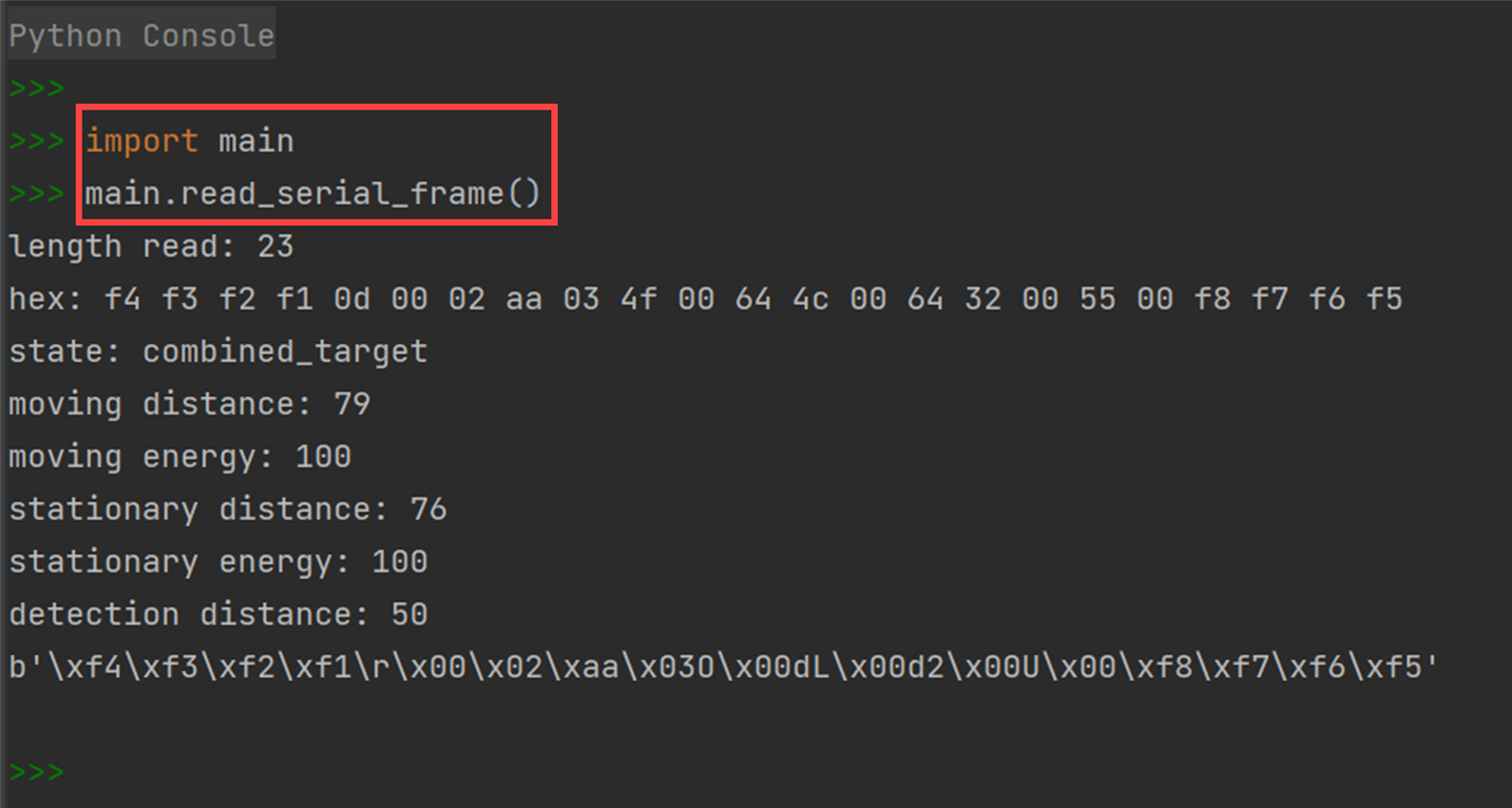
Here is an example report frame received over the UART connection, plus my interpretation of it:
Hex (23 bytes): f4 f3 f2 f1 0d 00 02 aa 03 4f 00 64 4c 00 64 32 00 55 00 f8 f7 f6 f5State: combined_targetMoving distance: 79Moving energy: 100Stationary distance: 76Stationary energy: 100Detection distance: 50
The first four bytes are a header, and the last four bytes are a terminator sequence. It is described in the user manual, but there are errors in the document, so I’m not 100% sure I have got everything else all correct.
In the Engineering mode, the same data as the Basic mode is provided, plus data for each range. The user manual can be used to figure it out.
Capturing and Decoding Reports using Python
I wrote simple Python code to capture the reports and decipher them. It's very prototype-grade code but is sufficient to see how to use the sensor.
You’ll need to install the PySerial package. To use the code, edit the line containing the text:
portname = 'COM5'
Set it to whatever COM port your carrier board or USB-Serial adapter uses.
To run the code, type the following in a Python command prompt:
import mainmain.read_serial_frame()
When that command is executed, the serial port will be opened, one frame will be captured, and the decoded output will be displayed.
Incidentally, the Python code can also switch to Engineering mode reports, by calling the main.enable_engineering() function, however I have not got around to decoding the received data for it (I don’t have a use for that currently). It will be straightforward to decode it in the same way that the basic decode is done, provided that the information in the user guide is correct.
Using an Arduino
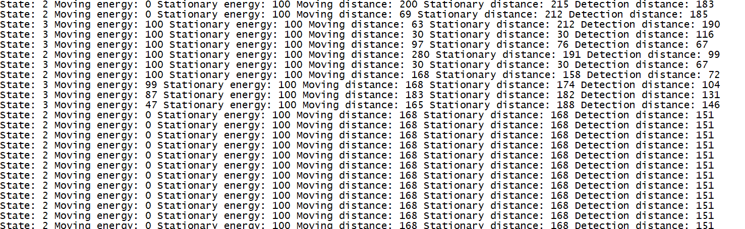
I decided to write some code to use the LD2410 with an Arduino. The code is on GitHub, and it requires any Arduino board with a serial interface called Serial1. The Serial1 pins are connected to the LD2410 board.
When run, the following output is displayed to the serial console:
Note that because the LD2410 consumes a fair amount of current, it is not recommended to power it from the 5V output from the Arduino. You may experience a temporary brownout when connecting it (I did).
Another key point is that some Arduino boards use 5V logic, whereas the LD2410 uses 3.3V logic levels. As a result, either use a 3.3V-compatible Arduino, or at the very least, just connect the LD2410 TX pin and not the RX pin, so that the LD2410 does not experience any 5V logic levels.
I only had one Arduino board to try it with; an Arduino Mega 2560. Unfortunately, it uses 5V logic levels. Although the code provides output as shown in the screenshot above, I’m not satisfied with it. Occasionally incorrect readings are obtained, and the code has some lines of sanity checking to throw out those readings and reattempt. I’ve not gotten to the bottom of it. Either my code has a problem, or the Arduino isn’t happy with the high data rate (256kbps; the LD2410 only supports this value), or there is a problem with the 3.3V logic levels (these are very close to the threshold that the ATmega chip supports). I didn’t troubleshoot further because I am unlikely to use the LD2410 with an Arduino. However, it is still “usable”, as the screenshot above shows. I recommend using the Pi Pico instead; see below.
Putting it all Together: Mouse Detector
This is a silly demo, but it shows the sensitivity of the system!
The Python code was adapted to MicroPython LD2410 code for the Pi Pico, and modified so that an LED would turn on whenever motion was detected. See here to learn about MicroPython.
The photo below shows the sensor connected to a Pico-Eurocard, but any Pico can be used.

The sensor easily detected the mouse whenever it was thrown into the range of the sensor!
Each time the mouse was thrown, the LED would briefly flicker on. I can conclude that the sensor would be pretty awesome for object or creature presence detection from rodent size upwards : )
The MicroPython LD2410 code is on GitHub. To use it, simply install the MicroPython environment on the Pi Pico, then upload the ld2410.py file to it (the steps to do this are documented on the Raspberry Pi website).
Note that you can change line 9 to select which GPIO pin the LED is connected to (the Pico-Eurocard uses GPIO22, or you can use GPIO25 on a normal standalone Pi Pico, or any other spare GPIO pin if you’re wiring an external LED).
Connect up the LD2410 RX pin to GPIO8, and the LD2410 TX pin to GPIO9, and connect up the GND and 5V wires.
Then, in the MicroPython console window, type:
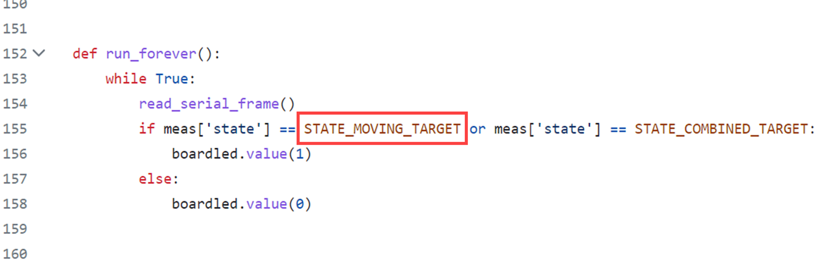
import ld2410ld2410.run_forever()
You’ll see debug on the screen, and the LED on the board with turn on when movement is detected. If you want to detect static objects, then change the text near line 155 from STATE_MOVING_TARGET to STATE_STATIONARY_TARGET.
Summary
The LD2410 is quite a nice board for detecting the presence of objects, including humans, in either static or motion states, and it is configurable to fine-tune the detection ranges. It can be set to be extremely sensitive if desired. I liked that the board is tiny, so it could be easy to conceal, making systems that are entirely invisible to users while performing valuable tasks.
It’s not too difficult to work with, but it's a real shame the documentation has so many errors. Other than that, the main negative point is the current consumption which is rather high at 80mA at 5V.
I also didn’t like that there was no way to turn off the sensor. Circuits will need a MOSFET if it is desired to send the sensor to sleep.
A minor negative point is that the serial interface data rate is unusually high at 256 kbps. I wish it was just 115200 bps, since that is a more popular value. Still, it was possible to use the board with Python code on the PC, as will as with an Arduino, and with a Pi Pico running MicroPython.
Thanks for reading!

