


This post explains the steps to debug shabaz' EZ-MCXN dev board in VS Code.
I propose a launch script for the NXP MCXN326 controller. Not dependent on MCUXpresso's IDE or VS Code extension. Also independent of dev board definitions and SDK example code files.
use of AI:
I used Google AI to learn what VS Code config needed to be created, to help create the scripts, resolve errors on the way, and to find the ARM 10-pin debug connector documentation.
It's not used to write this blog's content.
Prerequisites: What do you need:
- complete everything from previous post EZ-MCXN: CMake script for NXP MCXN326 controller.
- LinkServer installed
- a LinkServer debugger (I use the one on an NXP development board), and
- a cable to connect it to the EZ-MCXN SWD port
Scripts
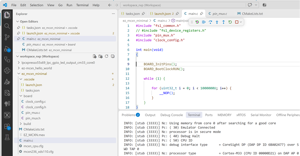
Debug configuration is defined in .vscode/launch.json. I started from existing LinkServer examples.
{
    "version": "0.2.0",
    "configurations": [
        {
            "name": "LinkServer: Debug MCXN236",
            "type": "cortex-debug",
            "request": "launch",
            "servertype": "external",
            "gdbTarget": "localhost:3333",
            "cwd": "${workspaceFolder}",
            "executable": "${command:cmake.launchTargetPath}",
            "device": "MCXN236",
            "interface": "swd",
            "runToEntryPoint": "main",
            "gdbpath": "arm-none-eabi-gdb",
            "svdFile": "${command:cmake.buildDirectory}/MCXN236.xml",
            "preLaunchTask": "Start LinkServer",
            "showDevDebugOutput": "none"
        }
    ]
}
It's similar to many debug configurations. It's able to flash the firmware, connect to the MCXN236 ARM core, and stop at the first line of code.
What's specific to NXP, is that the LinkServer service needs to be started before the debugger can be launched. That's done with a task. Tasks are defined in .vscode/tasks.json:
{
    "version": "2.0.0",
    "tasks": [
        {
            "label": "Start LinkServer",
            "type": "shell",
            "command": "C:\\NXP\\LinkServer_26.9.130\\LinkServer.exe",
            "args": [
                "gdbserver",
                "--gdb-port", "3333",
                "--probe", "FSAVAQEQ",
                "--no-boot",
                "--core", "cm33",
                "MCXN236:FRDM-MCXN236"
            ],
            "isBackground": true,
            "dependsOn": [
                "CMake: build"
            ],
            "problemMatcher": {
                "pattern": {
                    "regexp": "^$"
                },
                "background": {
                    "activeOnStart": true,
                    "beginsPattern": ".*",
                    "endsPattern": ".*GDB server listening on port *"
                }
            }
        }
    ]
}
In the launch config, this task is listed as a precondition:
"preLaunchTask": "Start LinkServer",
The task is will kick of LinkServer in the background, and yield back to the debug launcher, when it detects that the service is live:
"background": { "activeOnStart": true, "beginsPattern": ".*", "endsPattern": ".*GDB server listening on port *" }
LinkServer knows that it can stop running after the debug session is finished, when the underlying gdbserver is stopped.
It may sound a bit involved. But for the developer, the only thing to do is push the debug button.

Firmware is built if needed. The device is flashed. The LinkServer starts, and the debug session is initiated.
You can now step through code, watch variables, check registers.
Debugger and connection
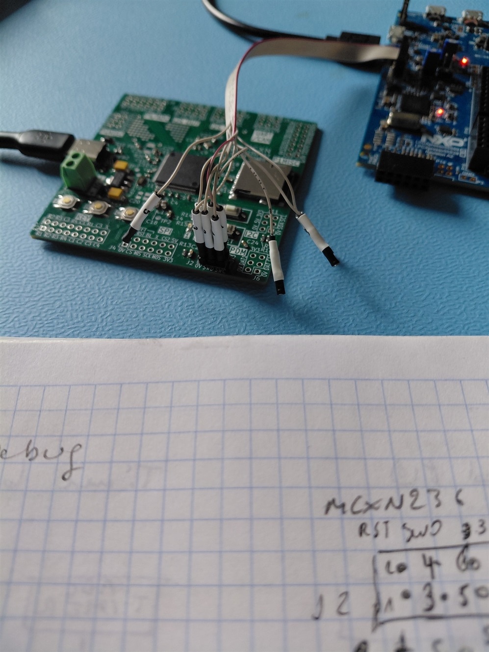
Debugger
I'm using an NXP LinkServer debugger with an ARM-CORTEX 10pin SWD connector.
The one I use is on board of NXP's lpcxpresso55s69 development kit from RoadTest AVNET Monarch LTE-M Development Kit -- EU (debugger breakout instructions).
e14 sells several debugger, e.g.: this affordable one: MCU-LINK Debugger Probe .
Connections
The EZ-MCXN board has a SWD connector with all necessary pins. The layout isn't standard ARM-CORTEX, so I use a conversion cable (example: Black Magic 0.1" Pin Header JTAG Cable).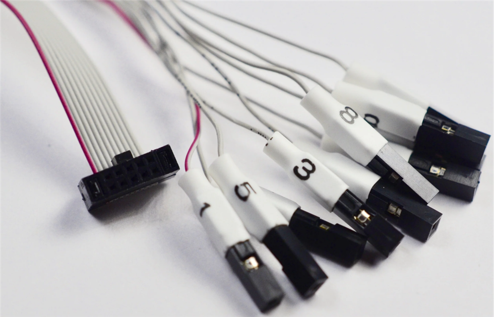
image source: product page I linked to above the image
ARM-CORTEX 10 pin SWD
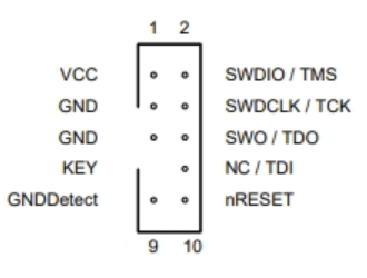
image source:NXP community
EZ-MCXN 6 pin SWD:
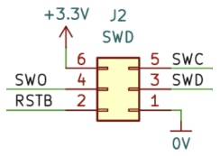
image souce: Shabaz' github
The wiring is easy: link these pins:
| function | debugger | EZ-MCXN | comments |
| VREF | 1 | 6 | this is voltage sense. You have to provide power to the EZ-MCXN, via its USB or J14 |
| SWDIO | 2 | 3 | |
| GND | 3 | 1 | |
| SWDCLK | 4 | 5 | |
| SWO | 6 | 4 | |
| nReset | 10 | 2 |
|
Debugger UART port If you use a standalone debugger, it will have dedicated UART TX / RX pins. Use those. No other actions needed. To use the LPCXpresso55S69 LinkServer UART backport: These lines are PCB-wired to the LPCX microcontroller's UART pins. You 'll need to hold that microcontroller in reset. P16: nRST to GND (keep dev board microcontroller asleep. It will not read nor drive the 2 UART pins. P1 should not have a jumper, because that disables the LinkServer UART. |
Thank you for reading
Project attached: ez_mcxn_minimal_20261112.zip
