


Table of Contents
Introduction
Recently, I wanted to play a little bit with audio projects, and noticed that NXP has some interesting new microcontrollers with just the interfaces I was hoping for. There are low-cost ready-made development boards for the MCXN range, but not for the particular package I was interested in, so I decided to make my own of sorts. In addition, I find I make less errors in future projects, if I take the time to produce a little test board for the microcontroller I plan to use. It’s a great opportunity to test out the CAD footprint, and decide what pins and peripherals to use, and determine the minimal viable circuit to bring up the part and program it.
This blog post details the test board I plan to make, in case anyone else is interested in this particular microcontroller too, and wishes to follow along. The KiCad project, footprint and other relevant files are all in an ez_mcxn project repository. Please note I have not tested this board yet, I have yet to receive the PCBs.
In a follow-up blog post I’ll explore how to build and run a demo app, assuming the hardware works!
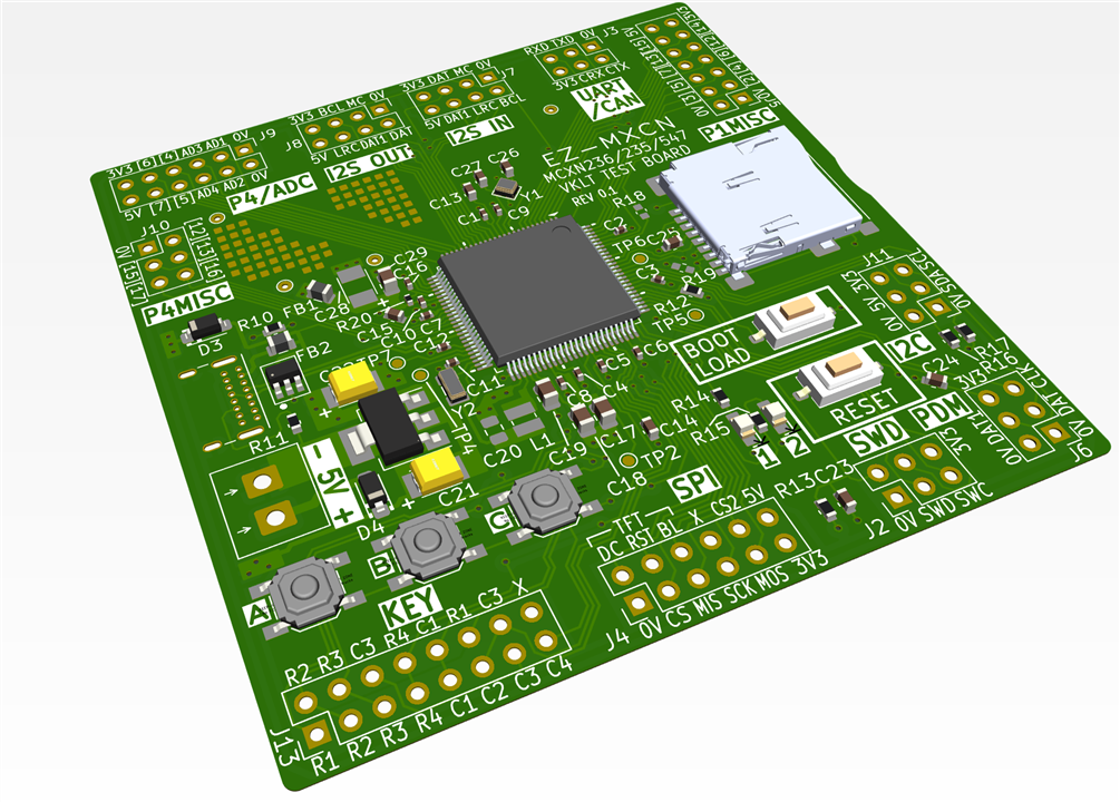
MCX Overview
According to NXP, MCX microcontrollers are intended for “simplified system design”. The MCX N-Series (which I plan to use; specifically the N23 series) offers high-performance, but there are other options, such as the general A-series, low-cost C-series, and wireless W-series. There are even some ultra-tiny 3 x 3 mm sized (QFN16 0.5 mm pitch) microcontrollers offered; the part I was interested in comes in a 100-pin QFP package.
The MCX parts have been around for just a year or two; I believe they contain a blend of older NXP LPC microcontroller features, along with Kinetis features from the Freescale acquisition (I’m basing this on the fact that I see lots of Freescale copyright notices in the SDK source code).
By “simplified system design” NXP may mean that the software development environment is a bit more modern (the old Eclipse platform is still offered, plus the usual IAR and Keil development environments, but now users can download and run using a VS Code plugin I believe; I decided to do things via the command line for now (apart from microcontroller configuration, for which I prefer the desktop graphical app from NXP, called MCUXpresso Config Tools. The app auto-generates source and header files which can be included within project builds.
Freescale microcontroller reference manuals used to be top notch, so I suspect that amount of documentation excellence may have been carried over onto the MCX series.
The SDK from NXP is called MCUXpresso SDK (HTML API Guide), and seems fine at first glance, I cannot comment much so far (I have built a blinky and a UART transmit project, but I have not explored further until I have hardware to try these things on). The NXP diagram below shows the functionality provided within the SDK.
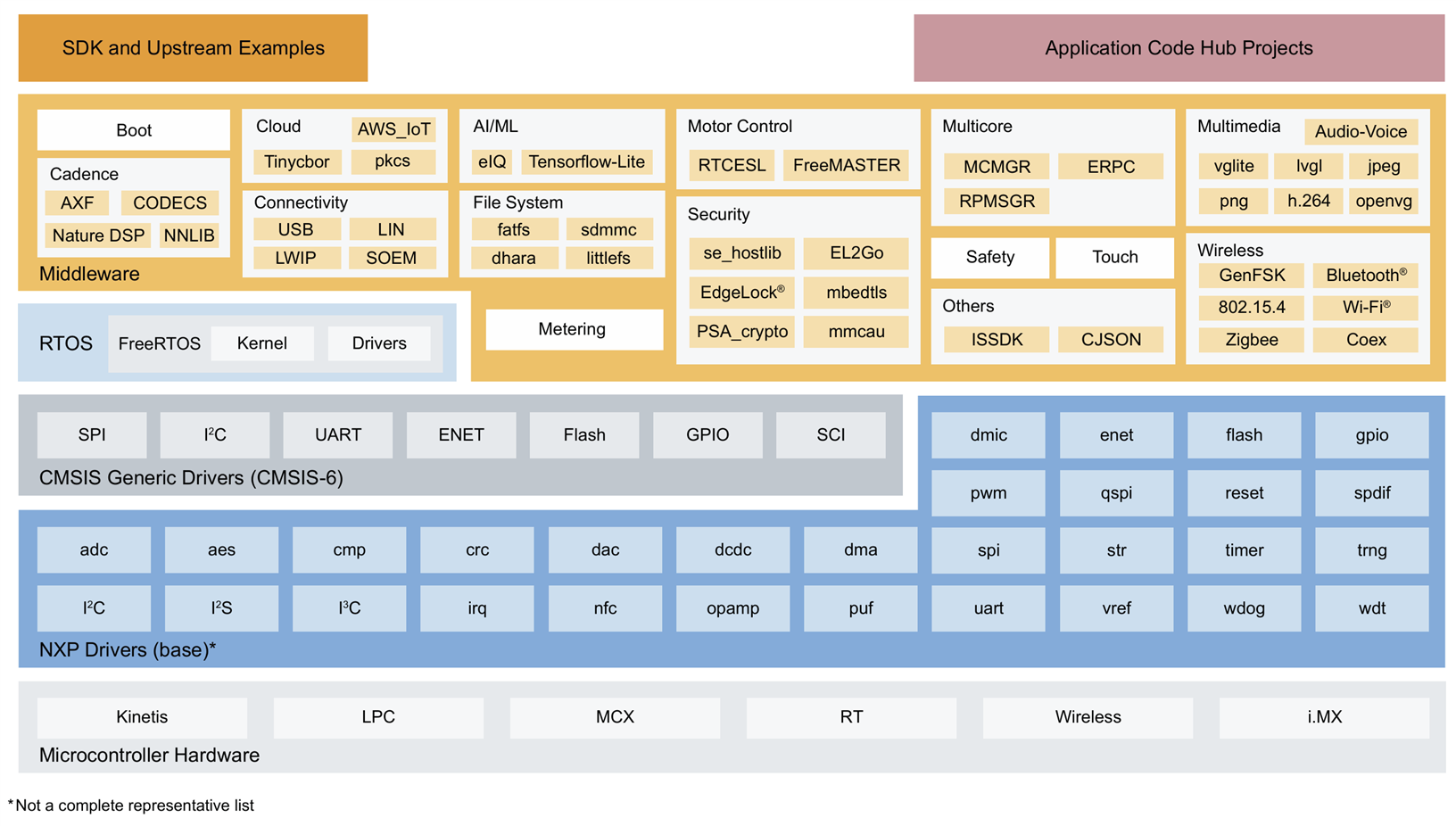
Image source: NXP
Since I was not interested in downloading a complete development environment, I just installed the MCUXpresso SDK using manual installation, and the MCUXpresso Config Tools app. I already had a compiler installed on my PC previously (called the ARM GNU Toolchain, downloadable from the ARM website).
My initial coding experiments are in the project GitHub repo, but have not been tested on real hardware currently. I plan to use a SWD CMSIS-DAP debug probe for firmware uploading/debugging, but direct upload is possible using the built-in bootloader within the microcontroller ROM. If you’re new to ARM devices, for an introduction to SWD and debug probes, see here: Using SWD with ARM Microcontrollers: An Introduction to Firmware Programming and Debugging!
MCXN236
The particular part I went for contains a Cortex-M33 core that runs at 150 MHz, 1 Mbyte Flash (their diagram below has a typo, it’s not 1 Mbit!), and RAM space totalling 352 Kbyte.
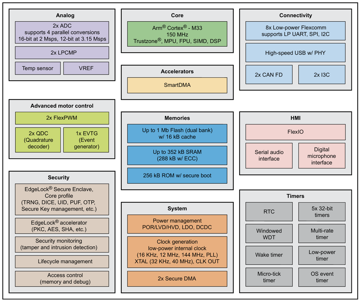
Image source: NXP
Many of the integrated features look very useful for a lot of projects. There is High Speed USB (480 Mbps), two simultaneous-sampling ADCs (great for measuring instruments, or even software-defined radio!), CAN FD interfaces, plus lots of audio interfaces (simultaneous I2S receive and transmit, plus up to 4 PDM MEMs mics). For more info, download the MCXN236 PDF Data Sheet, or the huge PDF Reference Manual. There is also a higher-end MCXN547 part that is (I believe) pin-compatible, with double the Flash, extra RAM, Ethernet, and dual-core.
The NXP development board for the MCXN236 (but in a different package) is called FRDM-MCXN236, and is quite low-cost in case anyone wants to immediately experiment with this part!
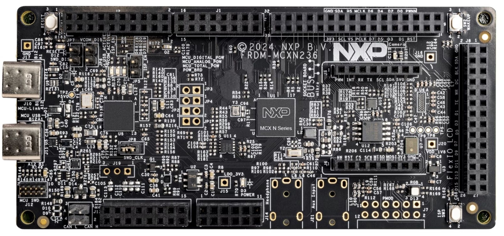
Image source: NXP
Circuit Diagram
The entire circuit diagram follows, but in bite-size pieces with explanation (the full KiCad source file is within the project repository).
Supply Decoupling
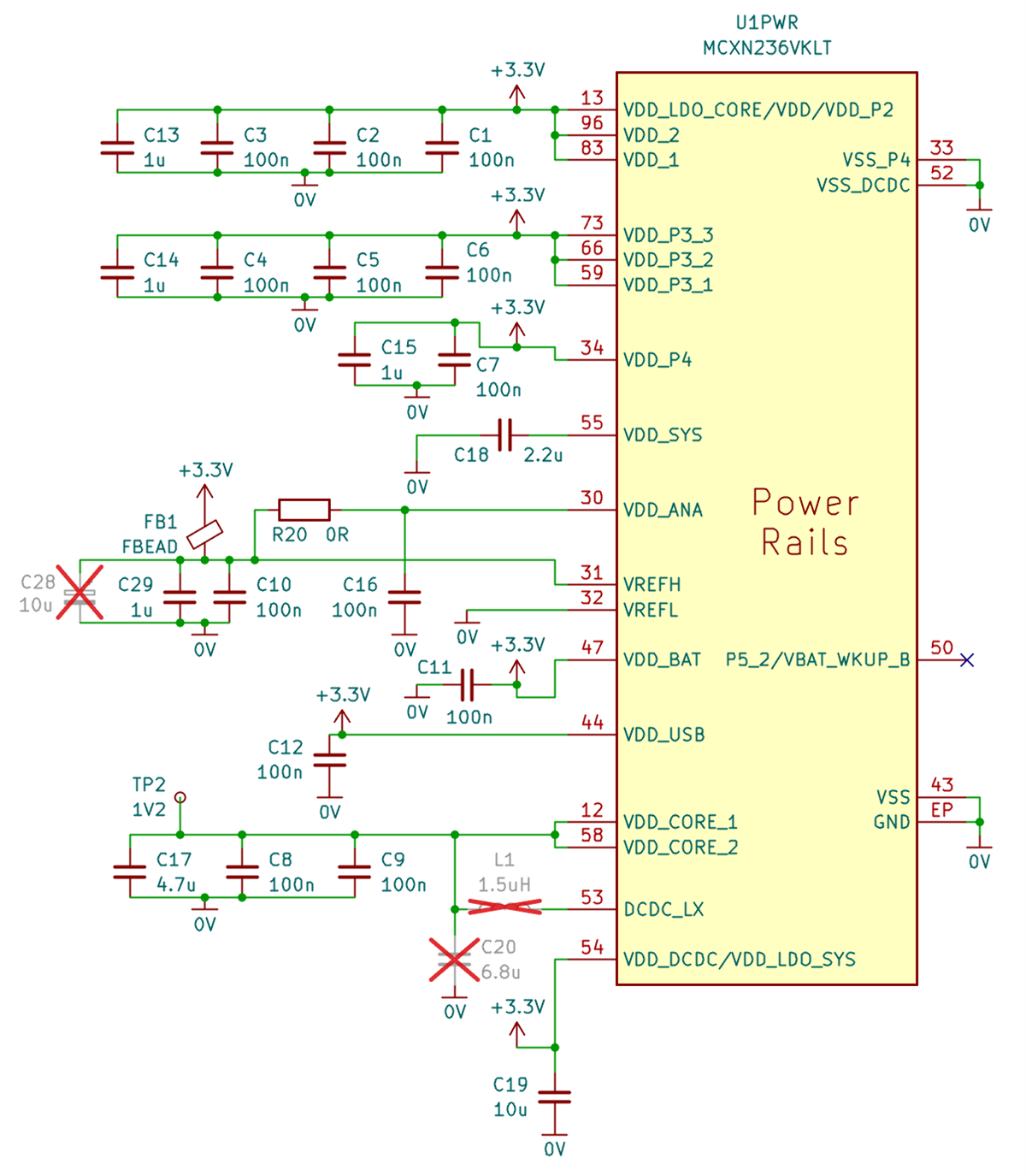
I decided to supply the microcontroller with a 3.3V source.
The package has 100 pins, and quite a lot of capacitors for power supply decoupling are needed, for some of the microcontroller internally generated rails as well as the 3.3V supply. Most of the 100nF capacitors are 0402-sized, to squeeze close to the microcontroller. There is an exposed ground pad on the underside of the package incidentally.
Some components are crossed out in red in the circuit below, for instance, L1 and C20 at pin 53 are omitted, they enable a DC-DC converter for greater efficiency, but I left those unpopulated to reduce noise since I may wish to experiment with the built-in ADC channels one day.
USB and Boot
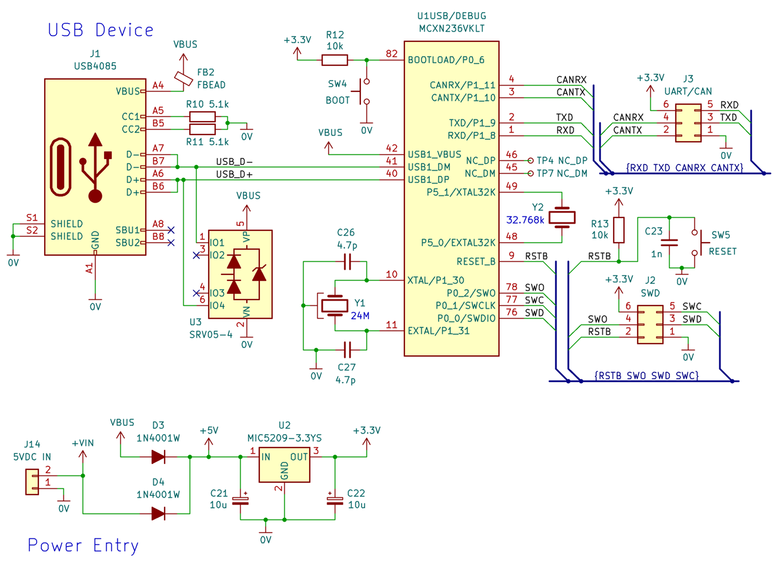
The 3.3V microcontroller supply comes from a USB socket (which provides about 5V), followed by a 3.3V LDO. Optionally, the 5V power entry can come from the screw-terminal connector J14, so it's not essential to power via USB.
The debug probe attaches to the SWD connector. If there is no debug probe, it is possible to upload firmware to the device via USB or UART [a USB-UART adapter would be used], by holding down the BOOT button while pressing RESET; there is NXP software to perform the firmware transfer from the PC in that case.
Audio Interfaces
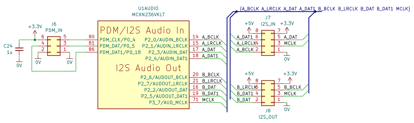
I used three connectors for the audio; PDM, and I2S (PDF I2S specification document) input and output. There is a second data line on each of the three connectors, i.e. the microcontroller supports up to four channels of audio (stereo per data signal) on each connector.
SPI, TFT, LEDs and Buttons: User Interface
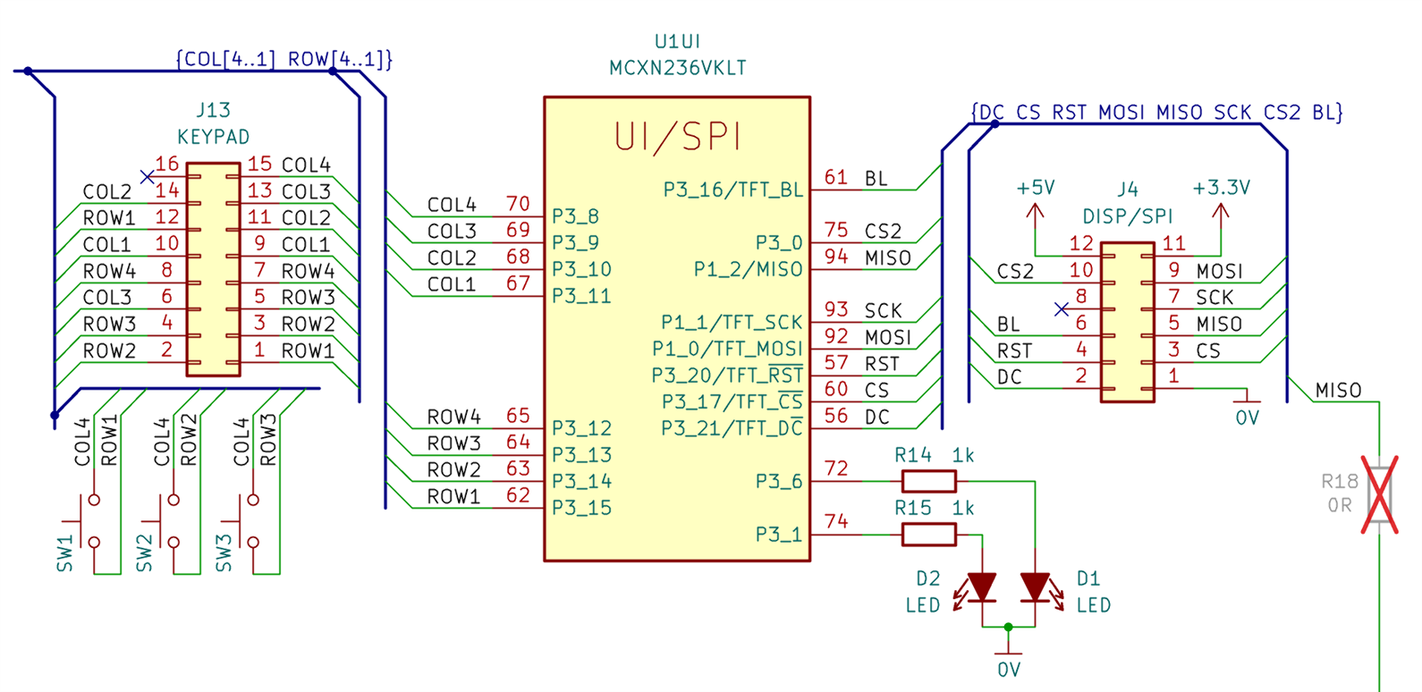
I wired the J13 header so that up to eight of the GPIO on port 3 could be used for keypad scanning. The pins are arranged so that typical 4x3 or 4x4 keypads should be able to easily connect, and there are three buttons on the PCB if no external keypad is used, and the GPIO could be used for other purposes if a keypad is not needed.
The SPI interface could be used to drive a TFT screen, or used for interfacing other devices. At the lower-right of the circuit in the diagram here, it can be seen that the MISO connection can optionally be routed elsewhere; that’s for making the board easier to use with the MCXN547 microcontroller, if Ethernet was required (unfortunately then the MISO line is no longer usable due to the particular set of pins chosen for the rest of the SPI interface; that won’t affect things if the SPI interface was used just for a display of course, as that would only require MOSI and not MISO).
There are two LEDs on the PCB attached to a couple of GPIO pins.
I2C and more SPI: microSD Card
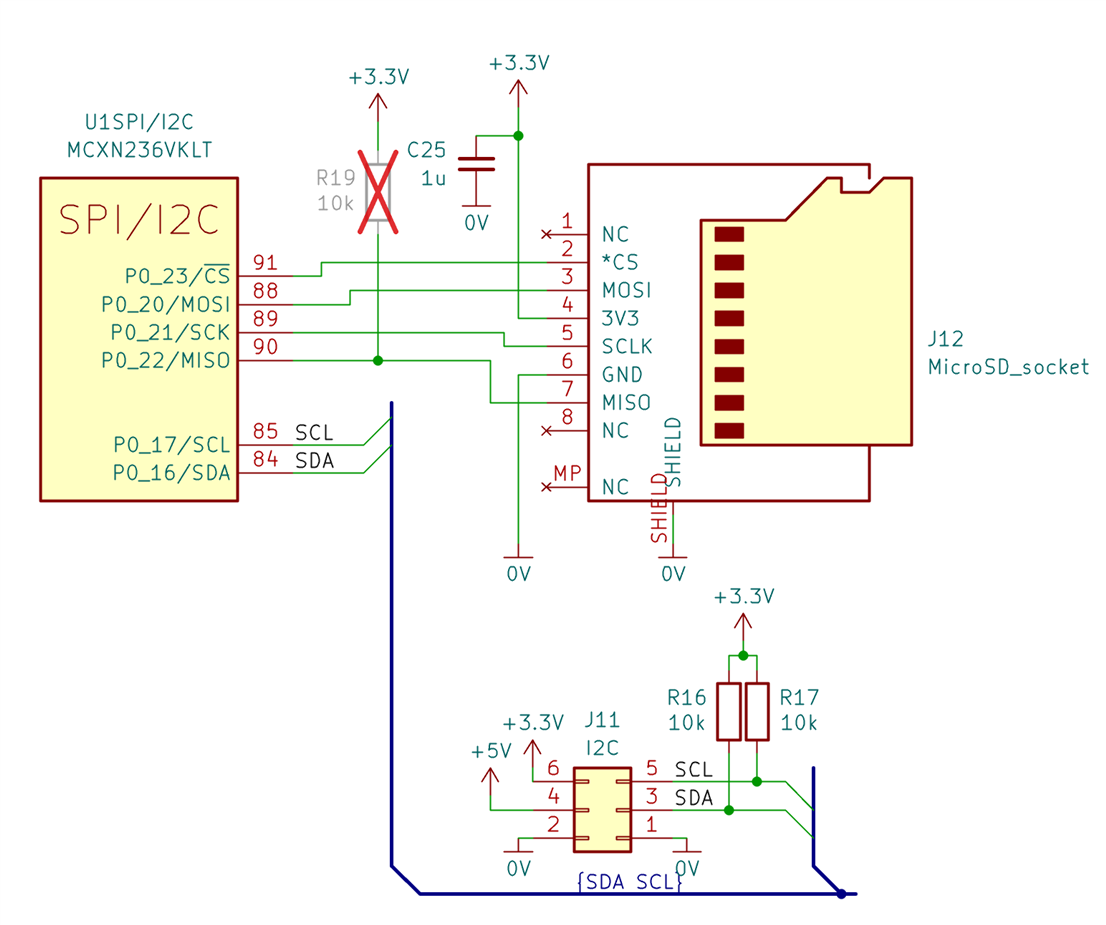
Another SPI interface was wired up to a microSD card socket, perhaps useful for audio file storage and so on (in the block diagram earlier, it can be seen that the SDK contains file system capabilities, so this should be straightforward to include into projects hopefully).
ADC and Spare GPIO Pins
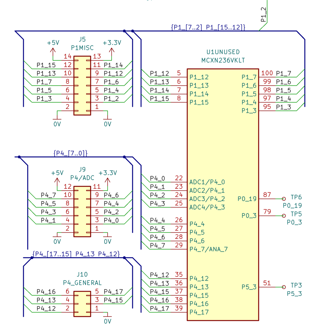
Nearly all remaining connections on the GPIO were wired to header pins. Header J9 (labelled P4/ADC) could be particularly useful, since a lot of the ADC inputs are available there. The P1MISC header J5 can be used for attaching an Ethernet PHY if desired, when using the MCX547 microcontroller. The P1_2 signal shown at the top-right of the disgram is wired (via a normally unpopulated zero-ohm resistor) to the SPI MISO connection mentioned earlier (that signal is repurposed for the Ethernet capability).
Board Layout and Parts List
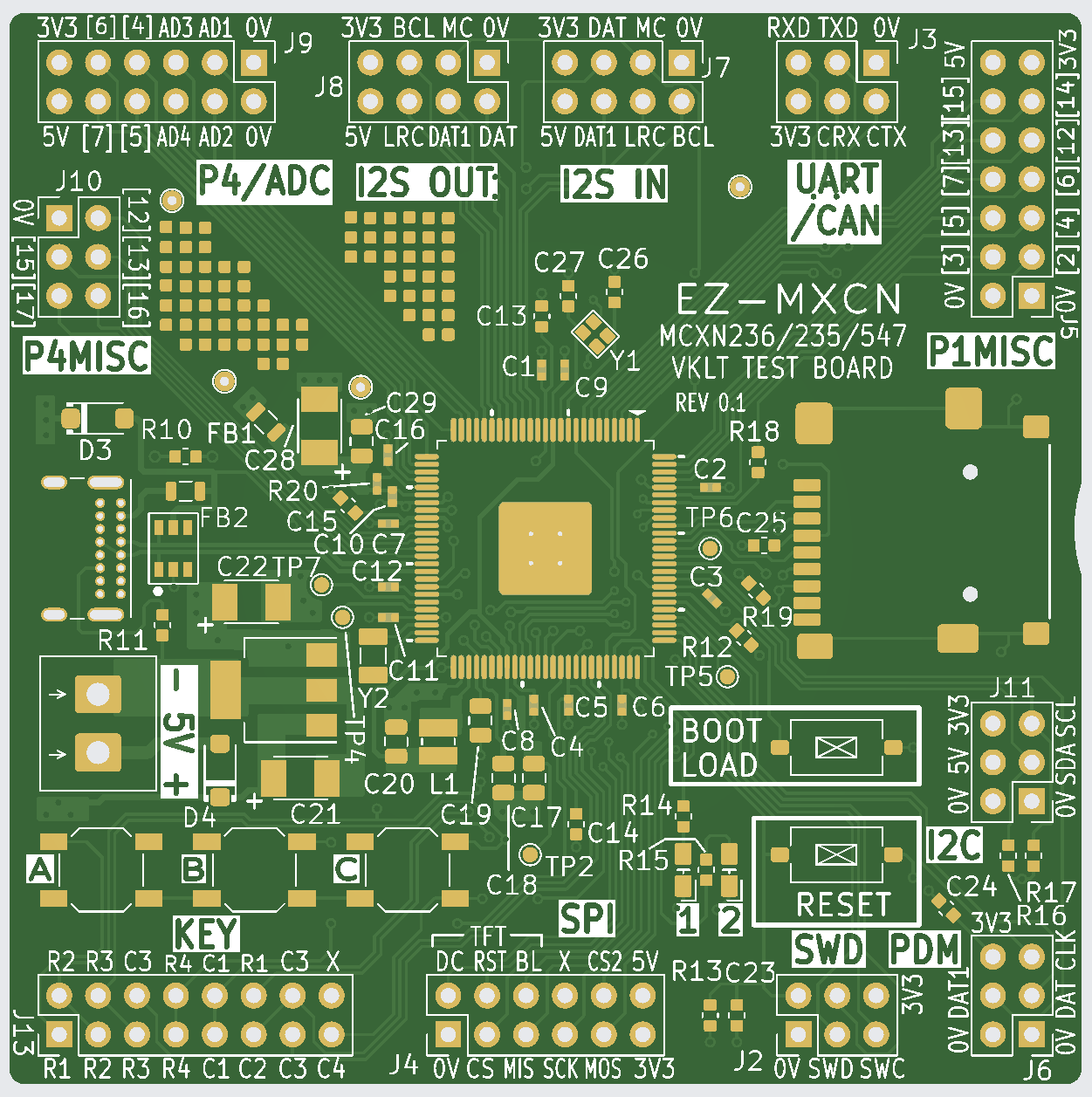
The board is 4-layer 70x70 mm, with mostly 0603-sized passives, but there are a few 0402-sized ones where space was constrained (particularly the many 100 nF decoupling capacitors are 0402-sized). I placed some bare SMD pads near the ADC header, in case small additions are required, for instance to supply power to the microcontroller ADC pin from a separate LDO.
For the parts list, see the Readme file in the project GitHub repo.
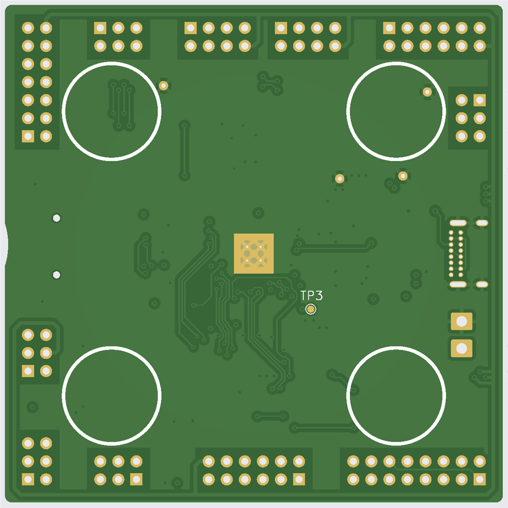
The underside has exposed copper to hopefully make it easier to hand-solder the microcontroller center pad. The inner layers are not shown, but they don't contain anything apart from 0V (layer 2) and 3.3V (layer 3).
Summary
The MCX series N microcontroller MCXN236 looks very useful for a lot of projects, so a little test board was designed, that brings out most of the connections to 2.54mm pin headers, and the project files (including Gerber files) are in the project GitHub repo.
If things don't go wrong, the next blog post, hopefully in a few weeks time, will cover board bring-up and a bit of coding.
Thanks for reading!
Top Comments