


Table of Contents
Introduction
The Renesas RA series of ARM Cortex-M4 microcontrollers have a lot of excellent integrated peripherals. In a previous blog post called Working with the Renesas RA4M1 Microcontroller a ‘general timer’ peripheral was used for general timing purposes. The peripheral can also be used for PWM generation. The Renesas RA4M1 chip contains up to 8 such timers, with each one capable of generating two PWM outputs. This blog post discusses how to use it.
This is the fourth blog post in a short RA4M1 series. To see the entire RA4M1 series, click here. This short blog post is written with the assumption that the first blog post has been read.
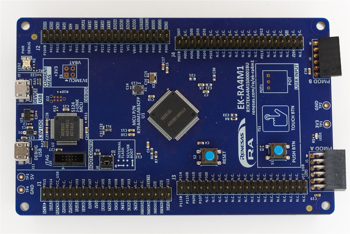
The easiest way to get going with the RA4M1 microcontroller is to obtain an evaluation board. In the future, there will also be an Arduino Uno R4 that will use this microcontroller too (although it will be a 64-pin version instead of the 100-pin one on the evaluation board).
Timer Modules
There are various timer modules inside the RA4M1, but the ones of interest for this blog post are known as GPT, which is the general-purpose timer suited for PWM. The diagrams below are from the RA4M1 user manual.

Two of the GPT timer modules are 32-bit, but I just used one of the 16-bit timer modules.

The modules are highly configurable as can be seen from the amount of registers. Fortunately, absolutely zero configuration code needs to be typed since the PWM capability can be configured from the development environment’s in-built utility called FSP (short for Flexible Software Package), which auto-generates the source code that contains the configuration.
Configuring the Timer Peripheral
As with all other peripherals, use the FSP Configuration pane (see the earlier blog post for information on this) to click on New Stack->Timers->Timer General PWM to add a stack. This particular timer peripheral is called r_gpt and you can search for it in the RA4M1 user manual, and the FSP API documentation to learn more about it.

Next, in the same way that peripherals were configured in the previous blog post, click on Properties and configure as shown in the screenshot below.
As mentioned there are multiple timer module instances inside the microcontroller, and I wished to use PWM on pins labelled GTIOC4A and GTIOC4B, and so the value 4 needed to be selected at Module->General->Channel.
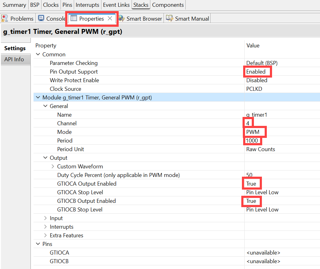
The PWM period is set with the Module->General->Period parameter in the screenshot above. By default the clock source is PCLKD which is set to 48 MHz on the RA4M1 evaluation board. So, if you want a PWM frequency of 10 kHz, then set the parameter to 48M/10k = 4800. I wanted a frequency of 48 kHz, so I set the parameter to 48M/48k = 1000.
Expand the Module->Pins section and click on the arrow icon as shown in the screenshot below:
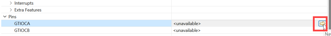
The FSP configuration pane will now show the pins list. Configure as shown in the screenshot below. I wanted to use both PWM outputs associated with the timer module instance for this example.

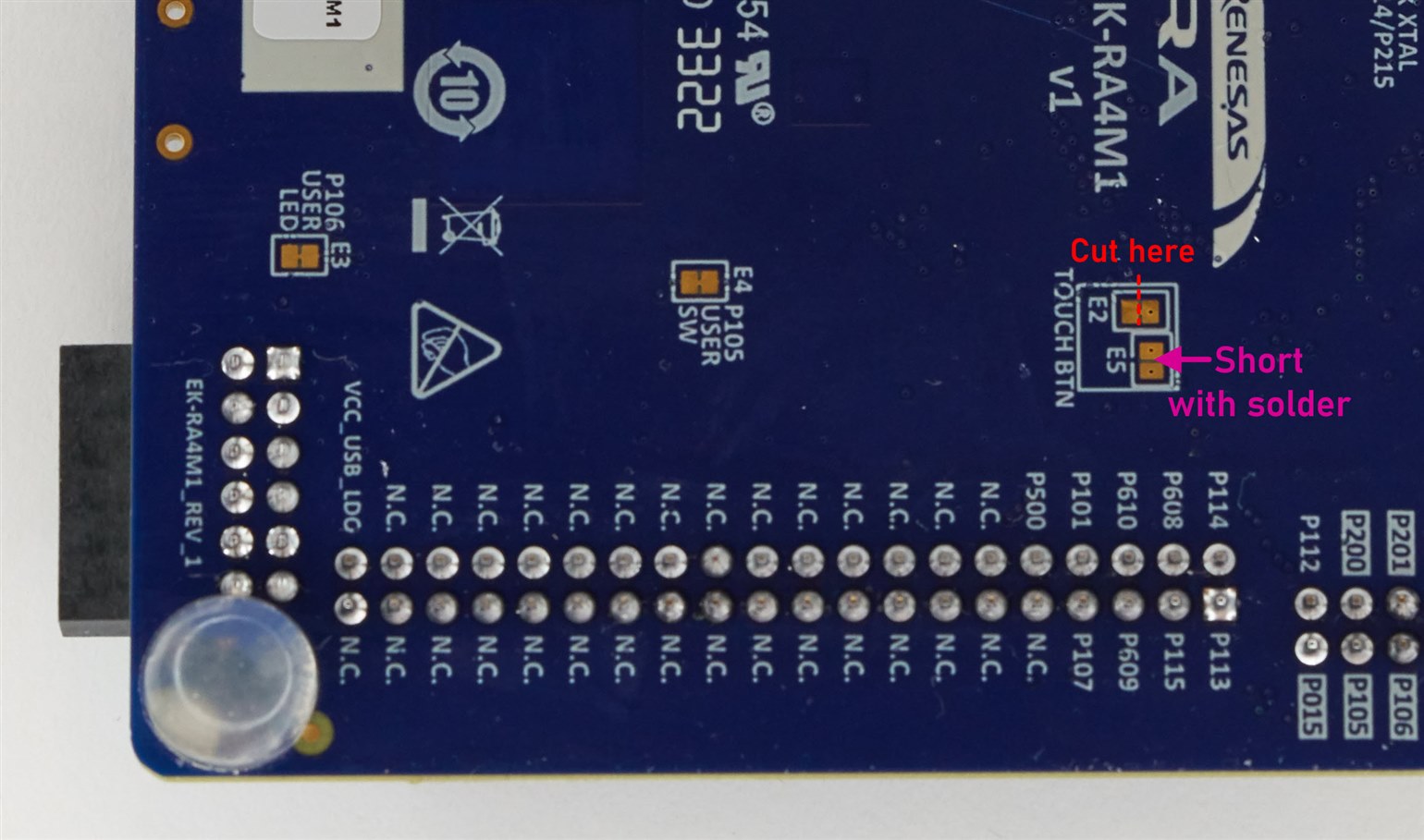
The RA4M1 evaluation board uses P115 for touch-button user input, which is not what I wanted. To disable the touch interface and use P115 for general I/O, cut the shorted pads labelled E2 on the underside of the board, and then bridge the pads labelled E5 with solder, so that they are shorted (see the photo below). Now the pin P115 is usable for PWM purposes.
Press Ctrl-S to save the FSP configuration, and then click on Generate Project Content, as discussed in the earlier blog post.
PWM Code
The API documentation (type r_gpt in the search box on that page) contains a complete example:

I took that example and converted it to a couple of functions. The pwm_init function is used to enable the two PWM outputs:
uint32_t pwm_periph_period;

void pwm_init(void)
{
    fsp_err_t err = FSP_SUCCESS;
    timer_info_t info;

    /* Initializes the module. */
    err = R_GPT_Open(&g_timer1_ctrl, &g_timer1_cfg);
    assert(FSP_SUCCESS == err);

    /* Start the timer. */
    R_GPT_Start(&g_timer1_ctrl);

    /* Get the current period setting. */
    R_GPT_InfoGet(&g_timer1_ctrl, &info);
    pwm_periph_period = info.period_counts;
}
The pwm_set function is used to program the duty cycle for either of the two outputs:
void pwm_set(uint8_t out_num, uint16_t pctx10)
{
    fsp_err_t err = FSP_SUCCESS;
    uint32_t width_cycles;
    gpt_io_pin_t io_name;

    io_name = GPT_IO_PIN_GTIOCA;
    if (out_num) {
        io_name = GPT_IO_PIN_GTIOCB;
    }

    /* Calculate the desired duty cycle based on the current period. Note that if the period could be larger than
     * UINT32_MAX / 100, this calculation could overflow. A cast to uint64_t is used to prevent this. The cast is
     * not required for 16-bit timers. */
    width_cycles = (uint32_t) (((uint64_t) pwm_periph_period * pctx10) / 1000);

    /* Set the calculated duty cycle. */
    err = R_GPT_DutyCycleSet(&g_timer1_ctrl, width_cycles, io_name);
    assert(FSP_SUCCESS == err);
}
The pwm_set function requires a value between 0-1000 to set the duty cycle to between 0.0 and 100.0%.
Here is the example code to set the PWM duty cycle to 5.5% for the first output, and 10% for the second output:
pwm_init();pwm_set(0, 55);pwm_set(1, 100);
Example Output
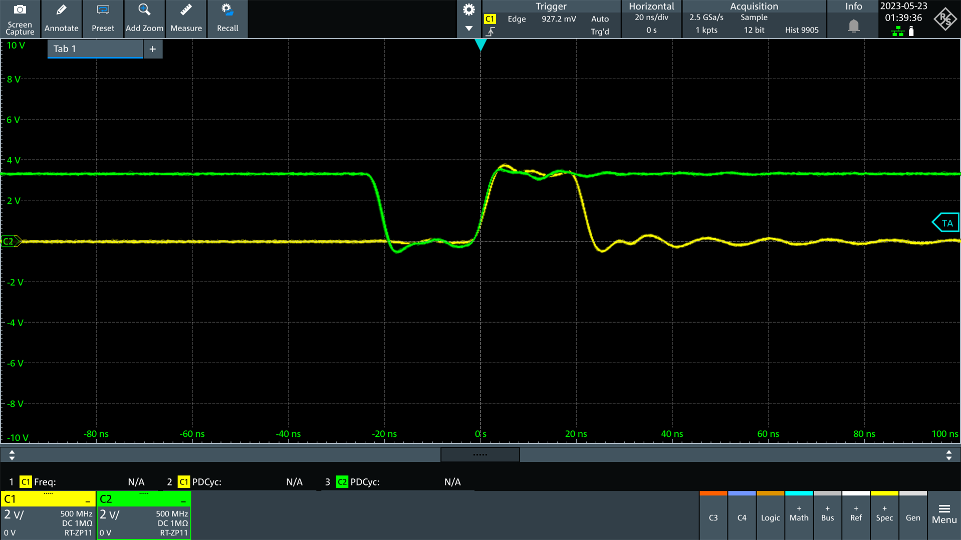
To test the code, I added the pwm_set function call into the USB code developed in the earlier blog post. By pressing keys on the PC, it was possible to adjust the PWM up or down. The screenshot below shows the PWM outputs set to 25.0% (yellow channel) and 75.0% (green channel):

With the 48 MHz clock sourced 48 kHz PWM rate, it is possible to have 0.1% duty cycle granularity which is great. The screenshot below shows the PWM rate set to 0.1% and 99.9% for the two outputs. The ripple is a result of probing and the long traces on the large development board.
Summary
The RA4M1 microcontroller has a lot of PWM capability, with up to 8 timer modules and 16 PWM outputs possible. It was very easy to configure, and a small amount of code was used to adjust the duty cycle. The PWM modules can also be used for more advanced stuff, such as driving brushless motors, and controlling MOSFETs with a configurable dead time.
Thanks for reading!


