


The DMA engine of the MSPM0 can move data between memory locations. In this example, a table of data is DMA-moved to the data register of the onboard 8-bit DAC. The name of the example in TI resource explorer is dac8_dma_function_generator.
Concept
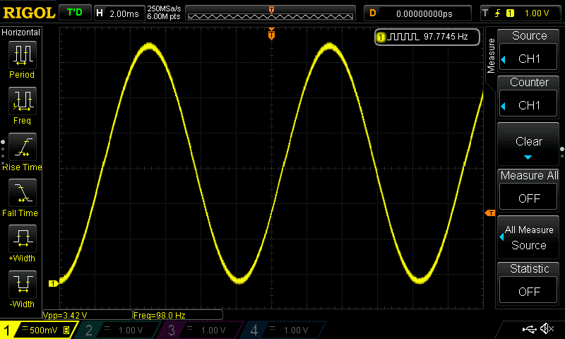
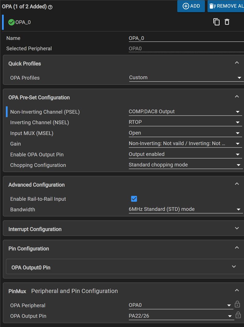
The source data for the DAC is an array of 256 samples of a sinus. One of the timers will tell DMA to copy the next value to the DAC's data register. The on-board OpAmp will buffer that data and expose it to pin 22, as an approx. 98 Hz sinus.

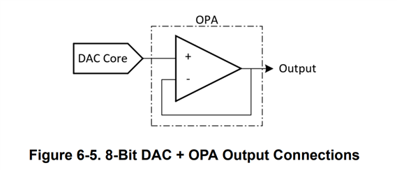
source: MSPM0 L-Series MCUs Hardware Development Guide
Configuration
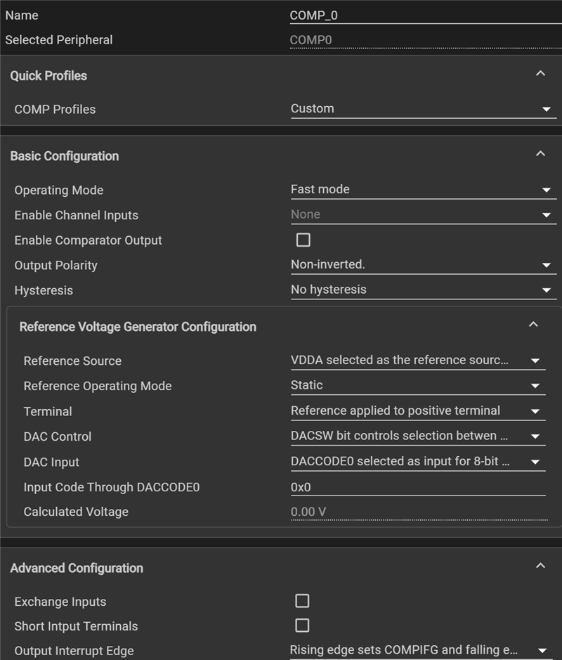
Because the DAC is part of the comparator peripheral, that comparator 'll be the object you configure:
OpAmp is configured to buffer and expose the DAC signal:
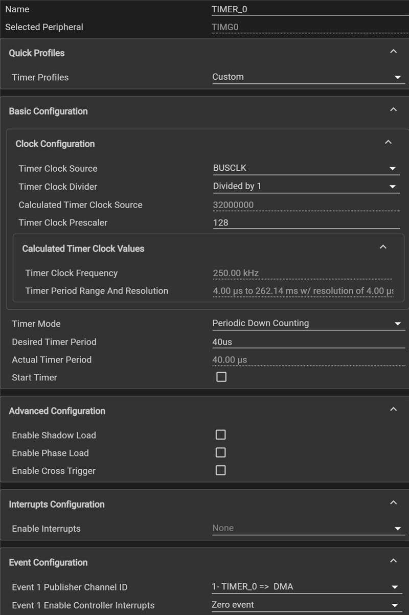
Timer is used to clock the move of the next sample. The 40 µs timer period drives the sinus frequency.
256 samples * 40 µs = 10240 µs -> 97.65625 Hz.
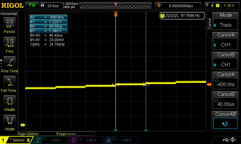
The MSPM0L uses an internal clock. This is not a crystal controlled frequency.
The DMA is then set up to transfer a table to a single destination, entry by entry (block to fixed):

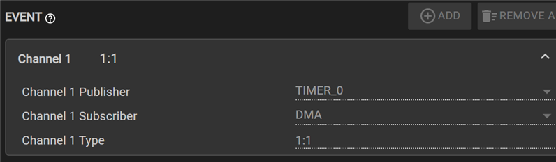
Last check, is to see the event handling
Code
The bulk of the work is in the peripheral configurations. The firmware itself does a few more setup tasks, then enables DMA and timer.
Then, the controller is put in a lower power mode (_WFI). All action happens in the TIMER, DMA, COMP blocks, pushed by the EVENT. Even if you halt the CPU with a breakpoint, the design keeps on working.
/* Array of samples for function stored in flash */
const uint8_t gSineArray[SINE_ARRAY_SAMPLES] =
            {
            0x80,0x83,0x86,0x89,0x8c,0x8f,0x92,0x95,
            // ...
            0x6a,0x6d,0x70,0x73,0x76,0x79,0x7c,0x80
            };

int main(void)
{
    SYSCFG_DL_init();

    /* Configure DMA to load samples from the gSineArray to the CTL3 register of COMP_0_INST */
    DL_DMA_setSrcAddr(DMA, DMA_CH0_CHAN_ID, (uint32_t) &gSineArray[0]);
    DL_DMA_setDestAddr(DMA, DMA_CH0_CHAN_ID, (uint32_t) &COMP_0_INST->CTL3);
    DL_DMA_setTransferSize(DMA, DMA_CH0_CHAN_ID, SINE_ARRAY_SAMPLES);
    DL_DMA_setSubscriberChanID(DMA, DL_DMA_SUBSCRIBER_INDEX_0, 1);
    DL_DMA_enableChannel(DMA, DMA_CH0_CHAN_ID);

    /* Start the timer counting, the zero event of this timer acts as the trigger for transfer */
    DL_TimerG_startCounter(TIMER_0_INST);

    while (1) {
        __WFI();
    }
}
Most of the MSPM0 posts in this series also work on the EasyL1105 board. This one is not portable, because the MSPM0L1105 doesn't have the comparator (and OpAmp).
