I reviewed the thermocouple cold junction compensation analogue circuit of the Renesas' starter kit (Road test: Renesas Solution Starter Kit for RX23E-A) in an earlier post. Here I'm checking how the firmware uses that compensation circuit to improve the accuracy of a K-type thermocouple.
I use cold junction temperature in this blog. A more correct name is reference junction temperature. cold junction compensation operates at 0°C. reference junction compensation operates at the temperature of the spot where the thermocouple meets the PCB copper.
Revisit the analogue circuit
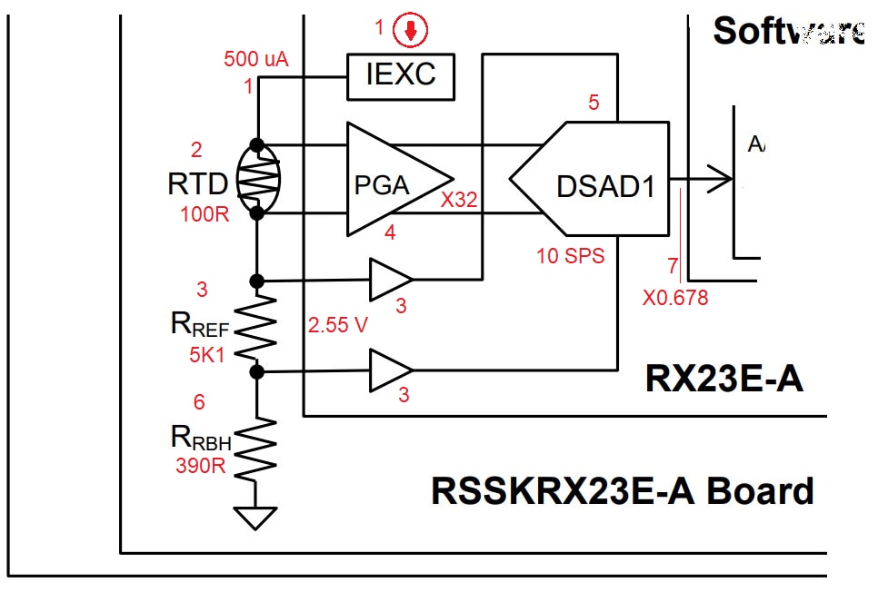
To paint the context, here's the schematics and a summary of the operation:
- the RX23E-A delivers the 500 uA constant current for what is essential 3 resistors in series.
- the 100R pt100 RTD resistance varies by temperature. Because of its placement on the board, it has the same temperature as the location where the thermocouple hits the copper (cold junction)
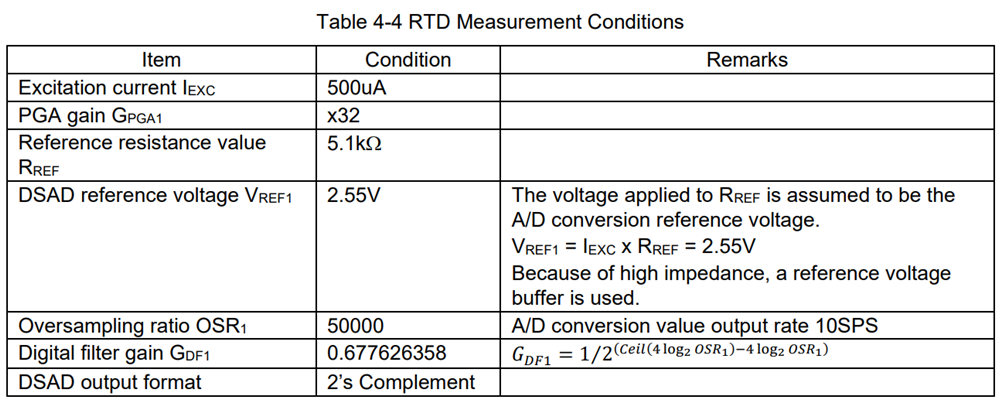
The voltage over the RTD is 500 uA x that resistance - The voltage reference for this circuit is generated by a 5K1 precision resistor that also has the 500 uA running through it. 5K1 x 500 uA = 2.55 V. Because both RTD and RREF are served by the exact same current (ratiometric measurement), noise is canceling itself out.
Because this is a high impedance voltage source, the reference voltage is buffered. - The gain amplifier for the RTD voltage is set to x32.
- ADC (over)samples, spawning results at 10 SPS
- RRBH lifts the reference voltage off ground, giving it some bottom-head-room (foot-room?).
- After sampling, the digital filter attenuates the results. It applies a gain on the sampled results of 0.678. If you run the calibration procedure of this firmware, this is the value that will be adapted based on the calibration outcome.

Firmware algorithm for compensation
The RDC voltage gets sampled together with the thermocouple's voltage. I will focus in this mail on how the junction temperature is derived. Then how this is applied to the thermocouple's algorithm.
First, the RTDs resistance is calculated based on the sample result.
All values, except DATARTD are given before in this post.
Once the resistance is known, two techniques are used to get at the temperature:
- there's a lookup able with resistance vs temperature, in 1°C steps, in the source code. The entry above and below the RRTD are looked up.
- linear extrapolation between those 2 table entries is used to calculate the temperature at RRTD. Here, the reasonable but not exact assumption is made that the small step change is linear.

Then the junction temperature gets calculated:
Last step is to convert that into reference junction thermoelectromotive force (in V). This is the same unit that will be used in the thermocouple's measurements.
In a next post I will review the thermocouple's algorithms. At that time, I'll point to the outcome that we reviewed here. Once I have a debugger working on the Starter Kit, I'll try to replay the calculations with real values. If that doesn't work out, I'll try to manually check based on the PC Tool register values...

-

scottiebabe
-
Cancel
-
Vote Up
0
Vote Down
-
-
Sign in to reply
-
More
-
Cancel
Comment-

scottiebabe
-
Cancel
-
Vote Up
0
Vote Down
-
-
Sign in to reply
-
More
-
Cancel
Children