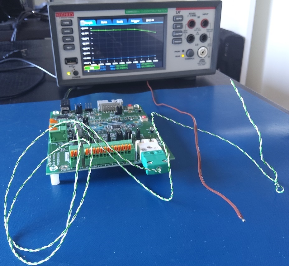
I Road Tested the Renesas' RX23E-A starter kit (Road test: Renesas Solution Starter Kit for RX23E-A). Now that the review is done, I can spend some time to go into the details. In this post, I'm checking how the firmware makes a precise temperature measurement with a K-type thermocouple.

I reviewed the thermocouple reference junction compensation in the previous post. That result will be used here to improve the accuracy of the thermocouple measurement.
Thermocouple schematic
The thermocouple gets a bias voltage of 2.5 V from one of the RX23E-A bias generators. The ADC reference voltage is generated internally by the controller too.

| The input filter isn't discussed in the application note. TI has a similar design, where the resistors and capacitors (differential mode filter and common mode capacitors) are reviewed. |
The front end amplifies the thermocouple signal 128 times. Digital filter gain is 0.678. Just like in the RTD circuit, this gain will be adjusted when you run the calibration function. And the (over)sampling rate is identical to the RTD too.
Temperature at the measurement point
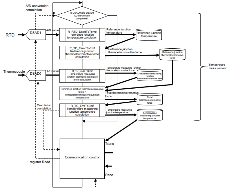
Algorithm:
All but the DATAMJ (sample) value are given above. It's the thermoelectromotive representation (V). This is the same unit we used to represent the reference junction temperature (VRJC) in the previous post.
Actual Temperature
We can now calculate the voltage representing the actual temperature, by including the reference junction value:![]()
Now, a conversion table can be used to translate the force into temperature. We look up the value before and after our calculated voltage, then use linear interpolation (again: same principle as in the previous post) to get at the temperature:
