element14 Community
element14 Community
    Register Log In
  • Site
  • Search
  • Log In Register
  • About Us
  • Community Hub
    Community Hub
    • What's New on element14
    • Feedback and Support
    • Benefits of Membership
    • Personal Blogs
    • Members Area
    • Achievement Levels
  • Learn
    Learn
    • Ask an Expert
    • eBooks
    • element14 presents
    • Learning Center
    • Tech Spotlight
    • STEM Academy
    • Webinars, Training and Events
    • Learning Groups
  • Technologies
    Technologies
    • 3D Printing
    • FPGA
    • Industrial Automation
    • Internet of Things
    • Power & Energy
    • Sensors
    • Technology Groups
  • Challenges & Projects
    Challenges & Projects
    • Design Challenges
    • element14 presents Projects
    • Project14
    • Arduino Projects
    • Raspberry Pi Projects
    • Project Groups
  • Products
    Products
    • Arduino
    • Avnet Boards Community
    • Dev Tools
    • Manufacturers
    • Multicomp Pro
    • Product Groups
    • Raspberry Pi
    • RoadTests & Reviews
  • Store
    Store
    • Visit Your Store
    • Choose another store...
      • Europe
      •  Austria (German)
      •  Belgium (Dutch, French)
      •  Bulgaria (Bulgarian)
      •  Czech Republic (Czech)
      •  Denmark (Danish)
      •  Estonia (Estonian)
      •  Finland (Finnish)
      •  France (French)
      •  Germany (German)
      •  Hungary (Hungarian)
      •  Ireland
      •  Israel
      •  Italy (Italian)
      •  Latvia (Latvian)
      •  
      •  Lithuania (Lithuanian)
      •  Netherlands (Dutch)
      •  Norway (Norwegian)
      •  Poland (Polish)
      •  Portugal (Portuguese)
      •  Romania (Romanian)
      •  Russia (Russian)
      •  Slovakia (Slovak)
      •  Slovenia (Slovenian)
      •  Spain (Spanish)
      •  Sweden (Swedish)
      •  Switzerland(German, French)
      •  Turkey (Turkish)
      •  United Kingdom
      • Asia Pacific
      •  Australia
      •  China
      •  Hong Kong
      •  India
      •  Korea (Korean)
      •  Malaysia
      •  New Zealand
      •  Philippines
      •  Singapore
      •  Taiwan
      •  Thailand (Thai)
      • Americas
      •  Brazil (Portuguese)
      •  Canada
      •  Mexico (Spanish)
      •  United States
      Can't find the country/region you're looking for? Visit our export site or find a local distributor.
  • Translate
  • Profile
  • Settings
Embedded and Microcontrollers
  • Technologies
  • More
Embedded and Microcontrollers
Blog Repairing a vacuum cleaner in the most complicated way (plus BQ25798 mini-review)
  • Blog
  • Forum
  • Documents
  • Quiz
  • Polls
  • Files
  • Members
  • Mentions
  • Sub-Groups
  • Tags
  • More
  • Cancel
  • New
Join Embedded and Microcontrollers to participate - click to join for free!
  • Share
  • More
  • Cancel
Group Actions
  • Group RSS
  • More
  • Cancel
Engagement
  • Author Author: vmate
  • Date Created: 22 Aug 2024 8:02 PM Date Created
  • Views 3165 views
  • Likes 13 likes
  • Comments 11 comments
  • charging
  • repair
  • embedded
  • battery
  • rp2040
  • microcontroller
Related
Recommended

Repairing a vacuum cleaner in the most complicated way (plus BQ25798 mini-review)

vmate
vmate
22 Aug 2024
Repairing a vacuum cleaner in the most complicated way (plus BQ25798 mini-review)

I have this battery powered vacuum cleaner that I quite like, but it decided to stop working.

It uses 3x 18650 cells for power, and has two brushed motors, one for sucking air, the second for a rotating brush in the bottom.

Vacuum cleaner in its "full" configuration

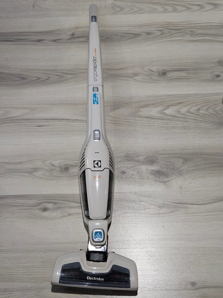
It can also be converted to a handheld vacuum:

Vacuum cleaner converted to handheld mode

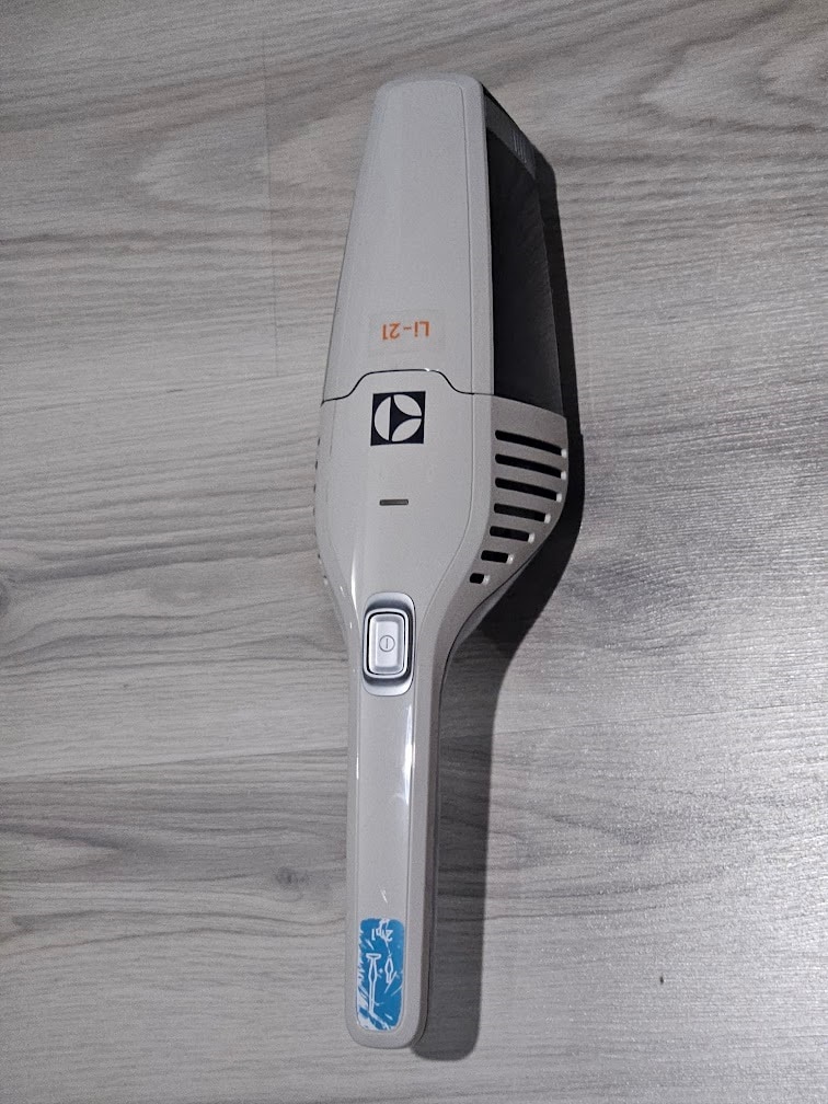
The thing is completely dead, it doesn't turn on, doesn't light up, doesn't charge, nothing.
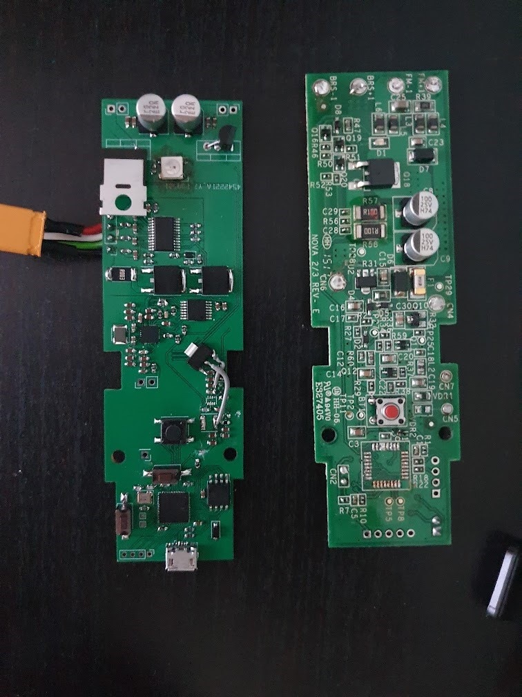
Took it apart, this is the PCB inside:


Original PCB

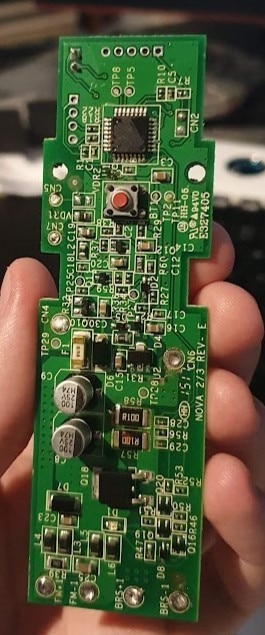
After some probing, it seems like the microcontroller is dead, so this entire board is trash.
I couldn't find a replacement one, so time to make something.

Custom PCB attempt 1

The functionality seems relatively simple:
- Charge/manage a 3S Li-Ion battery pack
- Turn the motors on and off

The sane way of doing this would probably be an off the shelf BMS with a charger module, and a relay + flip-flop to turn the motors on and off. That seems way too easy though, so doing it the hard way it is.


Here's the initial idea:

- BQ7791501 for battery balancing and protection. It's a neat little IC, supports 3-5S batteries, but multiple can be chained for larger packs. Does balancing and protection automagically without the need for a host microcontroller.

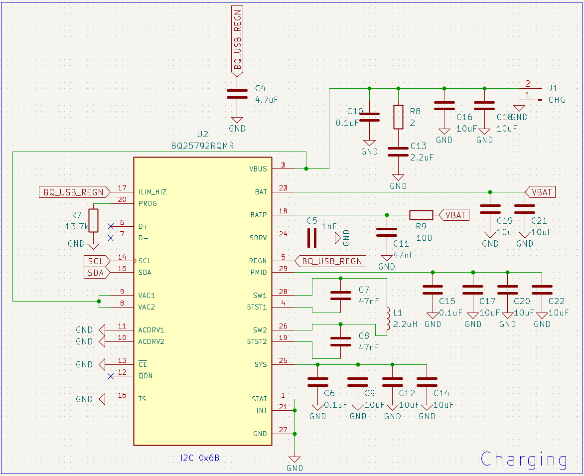
- BQ25798 for charging. I've had my eyes on this IC for a different project, so decided to test it out with this board. It takes 5-24V input, charges a 1-4S battery at 5A max, supports MPPT, has an ADC and can measure pretty much everything, all charging parameters and stages are configurable over I2C.  Saying that it's overkill for this application is an understatement, but maybe I'll really need MPPT solar charging for my vacuum cleaner one day.

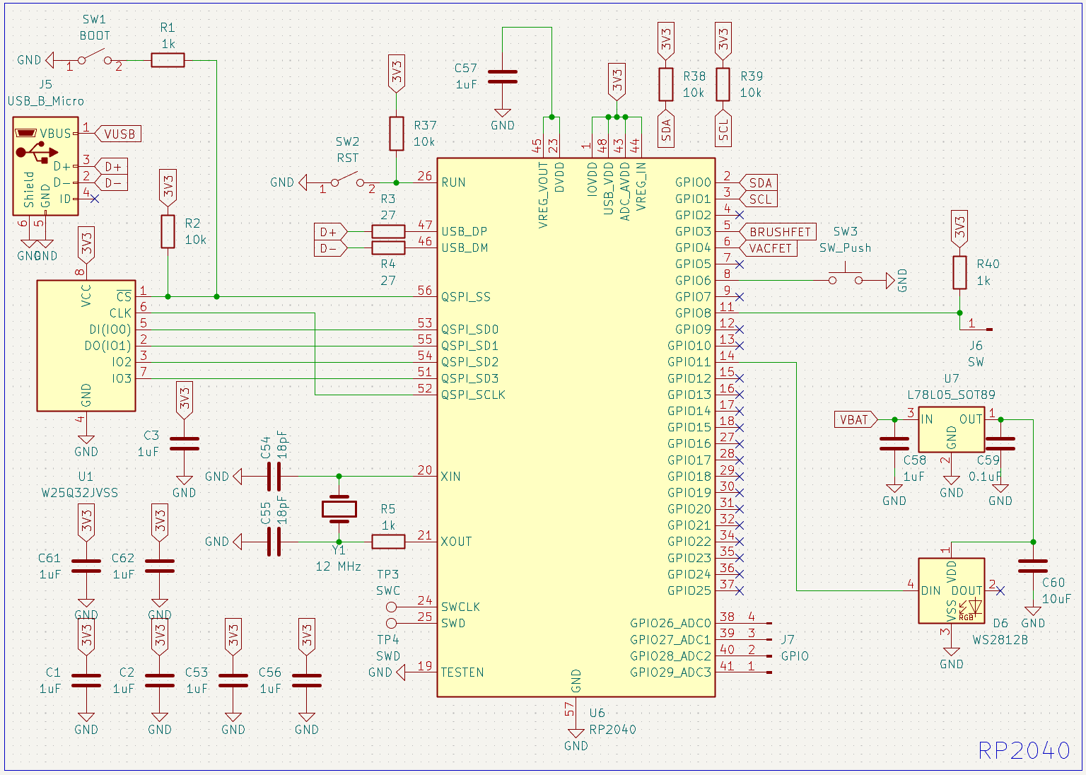
- RP2040 to control everything. Had a bunch of them, so why not. Pretty much any MCU would be sufficient for this project.

- Two MOSFETs to control the motors.


Some additional fancy features:

- WS2812B RGB LED instead of the single color one on the original board. There was no way to tell how charged up the battery was, which was quite annoying, so I wanted to use the RGB LED to indicate state-of-charge with colors.

- I didn't want to suffer trying to figure out battery state-of-charge manually, so I decided to use a BQ34Z100.

There are 4 contacts on the back of the unit:
Contacts on the base

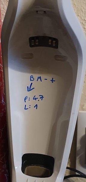
There's a common ground, charger input voltage, positive terminal of the brush motor in the bottom, and a pin coming from the two buttons at the top. Pressing the top button connects a 4.7k resistor between ground and this pin, while the bottom button uses 1k.

This is quite simple to use, I'll just need to make a voltage divider where one half is this 4.7k/1k resistor, and read the output voltage with the RP2040's ADC.

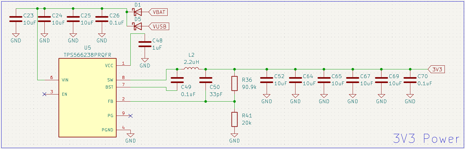
I also needed a 3.3V regulator to power things.

Here's the new PCB, next to the original one:


New and original PCBs

I somehow messed up the 3.3V regulator part, so bodged on a linear regulator instead.
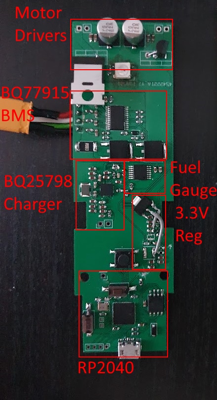
New PCB annotated with major functional blocks

Fuel gauge issues

Turns out, the BQ34Z100 was a horrible idea. It looked like exactly what I need, but after writing a bunch of code for it, I realized there were no registers for configuring cell parameters. The only way to do that, is to buy TI's very expensive proprietary programming dongle thing and use their software.

Since I messed up the 3.3V regulator, and the motor driver part was kinda horrible and underpowered as well, I decided to rework the board a bit, and order a new version.

Custom PCB attempt 2

- I switched out the regulator for an IC I've used before, a TPS566231.
- Found a promising fuel gauge, the MAX17261
- Also added an INA226 to monitor pack voltage and current, in case the new fuel gauge doesn't work out either, so I can try to calculate battery SoC in software on the RP2040 as a makeshift fuel gauge.
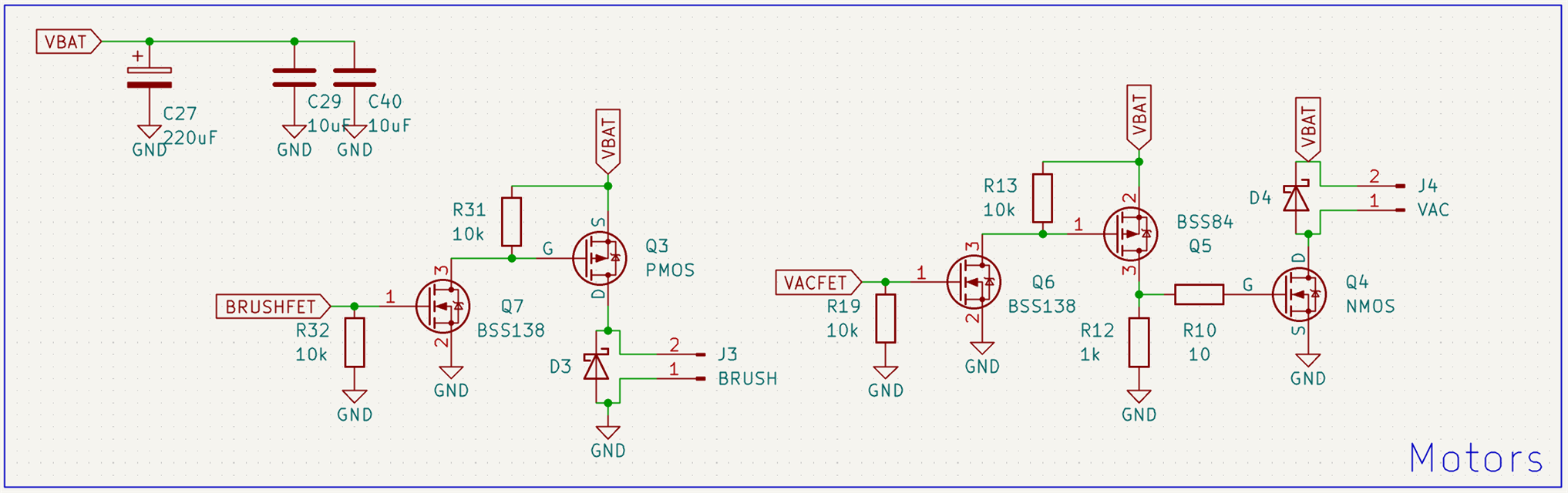
- Made a proper motor driver section. Instead of driving the FET gates at 3.3V, I added simple gate drivers with an N-channel/P-channel MOSFET pair, to be able to use the full battery voltage to drive the main FET gate. This also let me use way smaller and cheaper FETs for actually driving the motors.

This version finally seemed to work, other than a very slight, major issue with the fuel gauge/INA226. I wanted to share one shunt resistor for the BMS, fuel gauge, and INA226, which turned out to be a bad idea.

Schematic of BMS


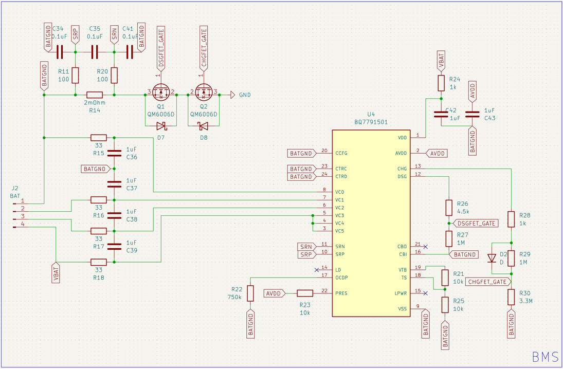
The BMS uses the battery pack's negative terminal as its ground, and the rest of the board is connected to pack ground through back-to-back N-MOSFETs, which the BMS controls.

Normally, this isn't a problem. The MOSFETs have very low on resistance, so pack ground and board ground is essentially the same. The issue is when the motors start running, and 15A goes through the two MOSFETs.

Each FET has an RDSon of 18mOhm, which means there will be a 0.54V drop through them when drawing 15A. Since the shunt resistor is before the FETs, it means there will be a common mode voltage of -0.54V at the two shunt input pins of the fuel gauge. The MAX17261 datasheet specifies an absolute maximum rating of -0.3V to Vbatt+0.3V.

The solution is to add a second shunt resistor AFTER the N-FETs. Fortunately, I was able to bodge in a new shunt and rewire the fuel gauge and INA226.

image

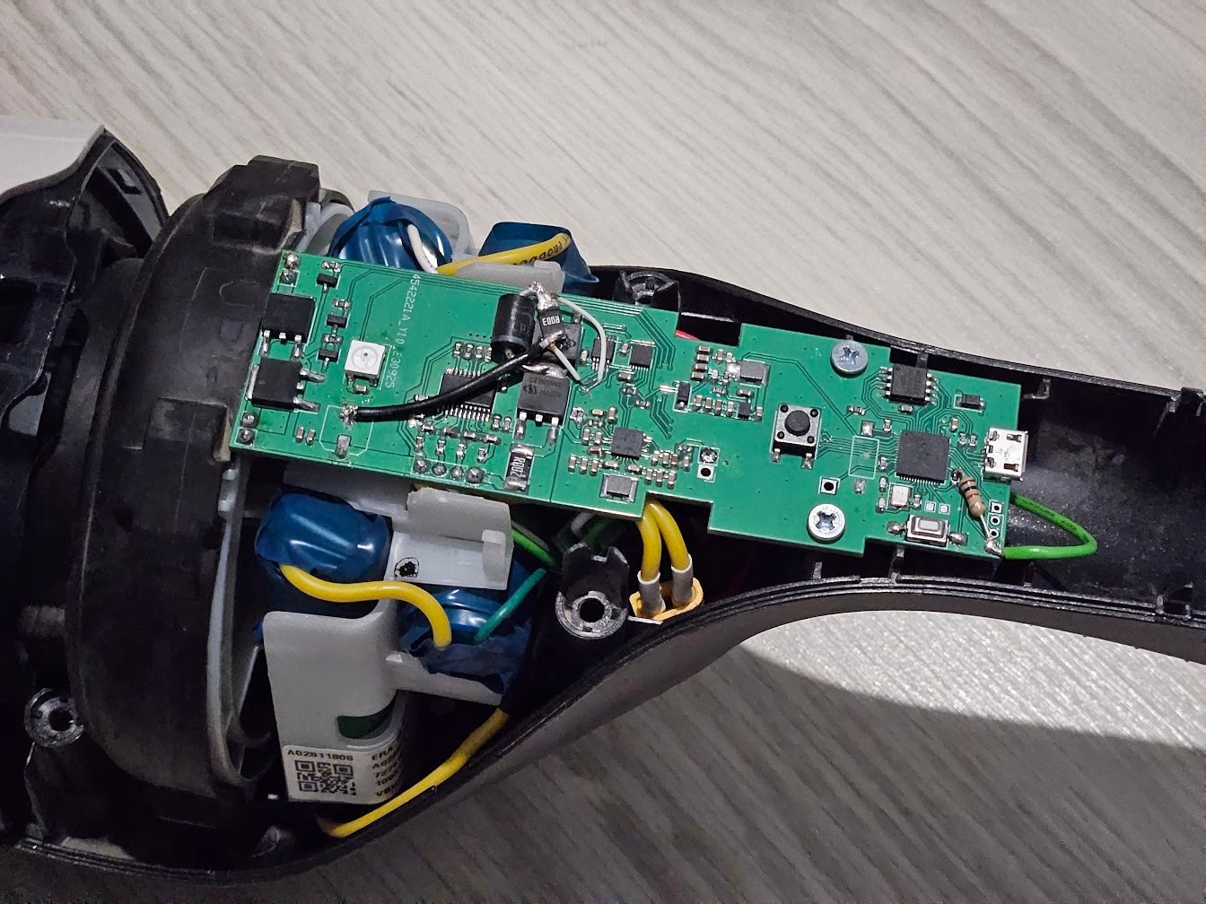
I completely forgot about the two buttons, but I did add pads for some unused GPIOs on the RP2040, and some of them happened to be ADC pins, so I only had to bodge a resistor on.

Here are the schematics for various parts of the PCB (I did not correct the shunt resistor issue here, so if you copy this, make sure to fix it as described above):

Motor driver schematic

Schematic of RP2040 microcontroller and various peripherals/misc devices

3.3V buck converter schematic

Schematic of fuel gauge and INA226

Charging circuit schematic

Software

I ended up writing a relatively feature-complete library for the BQ25798, I'll try and clean it up some time later and release it publicly for others to use.
The MAX17261 ended up working perfectly, although the datasheets were a bit disorganized.

The code isn't too complicated, all it has to do is read battery SoC from the MAX17261 and set the RGB LED to some color based on the value when the vacuum cleaner is on or charging. The power buttons simply toggle the two FETs on or off, the second button on the "base" switches to a "low power" mode by using 50% duty cycle PWM to drive the FETs instead of always on. Some parts of the code ended up a bit janky, so I'm not posting it (yet), if I have time to clean that up as well, I'll edit this blog to include it.

Conclusion

Overall, I'm very happy with how everything turned out, even though it would've probably been cheaper to buy another used vacuum cleaner. At least if anything fails now, I can fix it easier.

The MAX17261 "just works", doesn't have any over-complicated features, just set a few basic parameters and it gives you SoC.

The BQ25798 is amazing as well, the datasheet is great, every detail is explained superbly, all the registers are documented with examples, the IC is very configurable and easy to use, and does its job without any problems. All the charging states are configurable and can even be disabled completely, thanks to this I was able to reconfigure one of them to charge lead-acid batteries as well(this is officially not supported, only Li/NiMH). The built-in ADC can monitor input voltage/current, battery voltage, charging current, IC temperature, battery thermistor over I2C.

The only complaints I have about it are the package/footprint, and their MPPT implementation. There is no thermal pad at the bottom, so getting heat away from the IC is very difficult. It uses a weird TI package I've never seen before:
image
The lack of surface area for conducting heat away means it's basically impossible to cool the chip when it's doing over 3.5A output current. In a different project I'm working on, I tried to optimize the PCB layout for cooling, added a heatsink on top of the IC and on the underside of the PCB as well, with active cooling from both sides too, and the maximum I was able to achieve is slightly under 4A continuous. The IC claims to be able to do 5A max, so this is a bit disappointing.

Another slight annoyance is the MPPT implementation, instead of doing "true" MPPT, it measures open-circuit voltage of the solar panel every once in a while, and uses a percentage of that as the target voltage(this percentage, and the measurement interval are configurable over I2C). This works okay-ish, it's definitely way better than no MPPT at all, but "true" MPPT would be so much nicer(like the BQ25756 has).

  • Sign in to reply

Top Comments

  • michaelkellett
    michaelkellett over 1 year ago +1
    Thanks for sharing this. It's nice to see a real project, warts and all. I always tell customers to plan for at least one pcb iteration, it doesn't always happen but it often does. I'm puzzled - your…
  • scottiebabe
    scottiebabe over 1 year ago +1
    Wonderful project & write up. There is a good chance the battery charger is a flipchip QFN (FC-QFN or Hotrod QFN) https://www.ti.com/lit/an/slvaee1/slvaee1.pdf?ts=1724346665062 A low impedance thermal…
  • DAB
    DAB over 1 year ago +1
    Ah, but the adventure was priceless. Nice fix.
Parents
  • PORTS
    PORTS 27 days ago

    I fully appreciate you sharing your project with us. Congratulations on your initiative and your dedication to the project. I have two original Electrolux boards that are defective, but I couldn't find the electronic diagram or identify the chipset on the boards. Do you have any guidance regarding the possible repair of the original board?image

    • Cancel
    • Vote Up 0 Vote Down
    • Sign in to reply
    • More
    • Cancel
  • PORTS
    PORTS 27 days ago in reply to PORTS

    I forgot to mention: fully charged batteries, correct and checked connections, when connecting the battery pack a small current flows, but when pressing the pushbutton, the motor does not start. The fuse is okay.

    • Cancel
    • Vote Up 0 Vote Down
    • Sign in to reply
    • More
    • Cancel
  • vmate
    vmate 24 days ago in reply to PORTS

    I have absolutely no idea what to check, sorry. I did some basic testing on mine, all the obvious things were working, so came to the conclusion that the MCU is probably broken, and I can't fix that anyways. 

    I wasn't happy with the charging logic the original board used, so I gave up quite quickly on trying to fix it, and just made my own board.

    You could replace the original board without having to make a custom PCB, it's relatively simple to replicate its functionality with off the shelf modules. If you can find a 3S li-ion charger module, you have the difficult part done, then all you need is a BMS for the battery to cut it off when discharged too much(or maybe even a comparator circuit on top of it, that cuts off the battery at an adjustable voltage threshold level), and that's about it.

    For powering the thing, it's just two DC motors that you connect straight to the battery, you could use a simple DPST/DPDT switch to control them, if you drill a small hole in the housing, or use a simple flip-flop circuit plus a relay or FET switch for the motors if you want to keep the pushbutton for turning it on and off.

    • Cancel
    • Vote Up 0 Vote Down
    • Sign in to reply
    • More
    • Cancel
Comment
  • vmate
    vmate 24 days ago in reply to PORTS

    I have absolutely no idea what to check, sorry. I did some basic testing on mine, all the obvious things were working, so came to the conclusion that the MCU is probably broken, and I can't fix that anyways. 

    I wasn't happy with the charging logic the original board used, so I gave up quite quickly on trying to fix it, and just made my own board.

    You could replace the original board without having to make a custom PCB, it's relatively simple to replicate its functionality with off the shelf modules. If you can find a 3S li-ion charger module, you have the difficult part done, then all you need is a BMS for the battery to cut it off when discharged too much(or maybe even a comparator circuit on top of it, that cuts off the battery at an adjustable voltage threshold level), and that's about it.

    For powering the thing, it's just two DC motors that you connect straight to the battery, you could use a simple DPST/DPDT switch to control them, if you drill a small hole in the housing, or use a simple flip-flop circuit plus a relay or FET switch for the motors if you want to keep the pushbutton for turning it on and off.

    • Cancel
    • Vote Up 0 Vote Down
    • Sign in to reply
    • More
    • Cancel
Children
  • PORTS
    PORTS 22 days ago in reply to vmate

    Hello VMATE. I hope everything is ok with you.

    vmate: "I have absolutely no idea what to check, sorry. I did some basic testing on mine, all the obvious things were working, so came to the conclusion that the MCU is probably broken, and I can't fix that anyways."

    No problems my friend. I was also testing the components on the board and noticed that the voltage regulator was compromised and the microcontroller was no longer responding (with external power). I'm out of time, but I'm dying to draw up the electronic diagram for this board. Maybe in the future. :)

    vmate: "I wasn't happy with the charging logic the original board used, so I gave up quite quickly on trying to fix it, and just made my own board."

    Very good indeed. What problems did you encounter with the original charger? Your board looks great :)

    vmate:"You could replace the original board without having to make a custom PCB, it's relatively simple to replicate its functionality with off the shelf modules. If you can find a 3S li-ion charger module, you have the difficult part done, then all you need is a BMS for the battery to cut it off when discharged too much(or maybe even a comparator circuit on top of it, that cuts off the battery at an adjustable voltage threshold level), and that's about it. For powering the thing, it's just two DC motors that you connect straight to the battery, you could use a simple DPST/DPDT switch to control them, if you drill a small hole in the housing, or use a simple flip-flop circuit plus a relay or FET switch for the motors if you want to keep the pushbutton for turning it on and off."

    Great suggestion, my friend. I hadn't really considered this possibility. I focused on trying to repair the original board. The first one was already compromised. I ordered another one, which also came with a problem.

    I am really grateful for your attention in responding to my message and helping me try to revive the vacuum cleaner. :) Thank you very much.

    • Cancel
    • Vote Up 0 Vote Down
    • Sign in to reply
    • More
    • Cancel
element14 Community

element14 is the first online community specifically for engineers. Connect with your peers and get expert answers to your questions.

  • Members
  • Learn
  • Technologies
  • Challenges & Projects
  • Products
  • Store
  • About Us
  • Feedback & Support
  • FAQs
  • Terms of Use
  • Privacy Policy
  • Legal and Copyright Notices
  • Sitemap
  • Cookies

An Avnet Company © 2025 Premier Farnell Limited. All Rights Reserved.

Premier Farnell Ltd, registered in England and Wales (no 00876412), registered office: Farnell House, Forge Lane, Leeds LS12 2NE.

ICP 备案号 10220084.

Follow element14

  • X
  • Facebook
  • linkedin
  • YouTube