element14 Community
element14 Community
    Register Log In
  • Site
  • Search
  • Log In Register
  • Community Hub
    Community Hub
    • What's New on element14
    • Feedback and Support
    • Benefits of Membership
    • Personal Blogs
    • Members Area
    • Achievement Levels
  • Learn
    Learn
    • Ask an Expert
    • eBooks
    • element14 presents
    • Learning Center
    • Tech Spotlight
    • STEM Academy
    • Webinars, Training and Events
    • Learning Groups
  • Technologies
    Technologies
    • 3D Printing
    • FPGA
    • Industrial Automation
    • Internet of Things
    • Power & Energy
    • Sensors
    • Technology Groups
  • Challenges & Projects
    Challenges & Projects
    • Design Challenges
    • element14 presents Projects
    • Project14
    • Arduino Projects
    • Raspberry Pi Projects
    • Project Groups
  • Products
    Products
    • Arduino
    • Avnet Boards Community
    • Dev Tools
    • Manufacturers
    • Multicomp Pro
    • Product Groups
    • Raspberry Pi
    • RoadTests & Reviews
  • Store
    Store
    • Visit Your Store
    • Choose another store...
      • Europe
      •  Austria (German)
      •  Belgium (Dutch, French)
      •  Bulgaria (Bulgarian)
      •  Czech Republic (Czech)
      •  Denmark (Danish)
      •  Estonia (Estonian)
      •  Finland (Finnish)
      •  France (French)
      •  Germany (German)
      •  Hungary (Hungarian)
      •  Ireland
      •  Israel
      •  Italy (Italian)
      •  Latvia (Latvian)
      •  
      •  Lithuania (Lithuanian)
      •  Netherlands (Dutch)
      •  Norway (Norwegian)
      •  Poland (Polish)
      •  Portugal (Portuguese)
      •  Romania (Romanian)
      •  Russia (Russian)
      •  Slovakia (Slovak)
      •  Slovenia (Slovenian)
      •  Spain (Spanish)
      •  Sweden (Swedish)
      •  Switzerland(German, French)
      •  Turkey (Turkish)
      •  United Kingdom
      • Asia Pacific
      •  Australia
      •  China
      •  Hong Kong
      •  India
      •  Korea (Korean)
      •  Malaysia
      •  New Zealand
      •  Philippines
      •  Singapore
      •  Taiwan
      •  Thailand (Thai)
      • Americas
      •  Brazil (Portuguese)
      •  Canada
      •  Mexico (Spanish)
      •  United States
      Can't find the country/region you're looking for? Visit our export site or find a local distributor.
  • Translate
  • Profile
  • Settings
Embedded and Microcontrollers
  • Technologies
  • More
Embedded and Microcontrollers
Embedded Forum Very new design person here needing some input
  • Blog
  • Forum
  • Documents
  • Quiz
  • Polls
  • Files
  • Members
  • Mentions
  • Sub-Groups
  • Tags
  • More
  • Cancel
  • New
Join Embedded and Microcontrollers to participate - click to join for free!
Actions
  • Share
  • More
  • Cancel
Forum Thread Details
  • State Verified Answer
  • Replies 6 replies
  • Answers 3 answers
  • Subscribers 463 subscribers
  • Views 604 views
  • Users 0 members are here
  • pcb board
  • custom pcb
Related

Very new design person here needing some input

katghoti
katghoti over 7 years ago

I am creating a project that uses a Raspberry Pi Zero W and an ultrasonic distance measuring device (HC-SR04).  I have the code done, but now I want to move from the motherboard to a small PCB that will let me hook up the tester quickly.


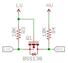
Here is a layout I pulled from the web that shows the need to split the signal back to ground to 3.3 volts do it doesn't fry the Pi.


image


So I took a stab a designing my first PCB using Autodesk eagle.  It was a struggle, but I think I got it done.  Here is a screenshot of the finished board


image


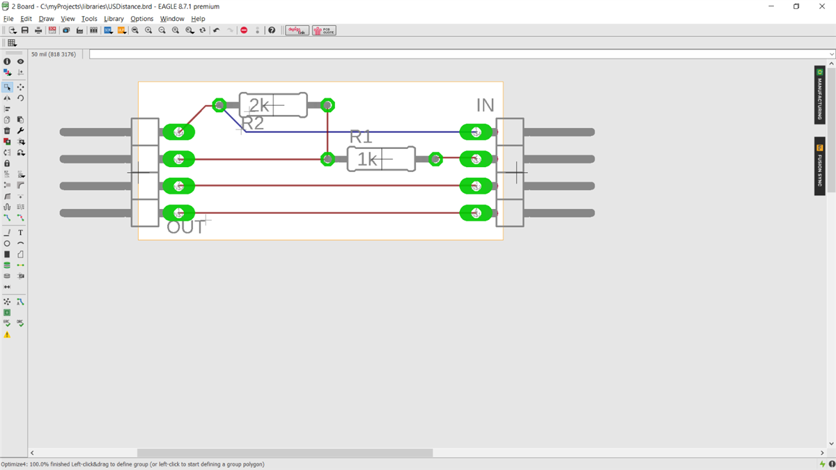
On one side I have the pins to match the Ultrasonic-module (IN) and one set of pins to go to the PI (OUT).  I am using a 1K AND 2K resistor on the advice of another post to split the signal back.  Before I send this out to get a PCP bid, can someone with vastly more knowledge than I look it over quickly and make sure this is correct according to the layout above.  I am working on a silkscreen layer for the pins on both sides to help with hookup, but right now I just need to know if I am on the right track.


Thanks.


John

  • Sign in to reply
  • Cancel

Top Replies

  • genebren
    genebren over 7 years ago +3 verified
    John, Your PCB looks OK. I say this not completely understanding which pins on your 'IN' and 'OUT' are assigned to. Just guessing at this point but the 'OUT' side looks like Ground, Echo, +5v or Trigger…
  • katghoti
    katghoti over 7 years ago in reply to thehwcave +3
    I had not considered this path. Although it was fun creating the PCB, I think I will take a look a this route. It looks less expensive and should do what I need. Thank you very much!. John
  • katghoti
    katghoti over 7 years ago in reply to genebren +2
    Yes the in side will match up (from the bottom up) +5V, Trigger, Echo, Ground coming from the ultrasonic tester. The out side will be 5V from the pi, GPIO PIN, GPIO PIN, Ground. The GPIO pins will vary…
  • genebren
    0 genebren over 7 years ago

    John,


    Your PCB looks OK.  I say this not completely understanding which pins on your 'IN' and 'OUT' are assigned to.  Just guessing at this point but the 'OUT' side looks like Ground, Echo, +5v or Trigger and +5v or Trigger (top to bottom).  On the 'IN' side it looks like Ground, GPIO24, +5v or GPIO23 and +5v or GPIO23 (again, top to bottom).  If these are correct, then I would say that you PCB looks fine.


    Good luck,

    Gene

    • Cancel
    • Vote Up +3 Vote Down
    • Sign in to reply
    • Verify Answer
    • Reject Answer
    • Cancel
  • katghoti
    0 katghoti over 7 years ago in reply to genebren

    Yes the in side will match up (from the bottom up) +5V, Trigger, Echo, Ground coming from the ultrasonic tester.  The out side will be 5V from the pi, GPIO PIN, GPIO PIN, Ground.  The GPIO pins will vary depending on what I use.  The example I pulled down used pin 23 and 24 as an example.  I am working on a silkscreen on the pins for clarity, and then I will look for a PCB company to make one up so I can test it.


    Thank Gene.

    • Cancel
    • Vote Up +2 Vote Down
    • Sign in to reply
    • Verify Answer
    • Cancel
  • thehwcave
    0 thehwcave over 7 years ago

    Hi John,

    just wondering, making a PCB for such a small circuit seems to be a lot of work. I would just use piece of Veroboard (aka stripboard) ...

    • Cancel
    • Vote Up +2 Vote Down
    • Sign in to reply
    • Verify Answer
    • Reject Answer
    • Cancel
  • katghoti
    0 katghoti over 7 years ago in reply to thehwcave

    I had not considered this path.  Although it was fun creating the PCB, I think I will take a look a this route.  It looks less expensive and should do what I need.


    Thank you very much!.


    John

    • Cancel
    • Vote Up +3 Vote Down
    • Sign in to reply
    • Verify Answer
    • Cancel
  • katghoti
    0 katghoti over 7 years ago

    FYI for anyone reading this post.  I found a company (https://aisler.net/ ) that I was able to upload my Autodesk Eagle file to and they are printing me 3 boards for 4.71 euro ($5.81) with free shipping to the states.  I am not affiliated with this company or site, I just found them when I was designing in Fritzing.  So now I should get this pcb in 6 - 8 days or so.  Again thanks everyone for the help, and I'll let everyone know what they look like when they get here.

    • Cancel
    • Vote Up +2 Vote Down
    • Sign in to reply
    • Verify Answer
    • Reject Answer
    • Cancel
  • mcb1
    0 mcb1 over 7 years ago

    Great find on the pcb company.


    The HC-SR04 states it is TTL and runs on 5V.

    I presume that you can drive the trigger pin using the 3v3.


    The alternative way to convert levels is these little things which can drive 220mA continuous or 880mA pulsed.

    https://www.sparkfun.com/products/12009

    Sparkfun are just one supplier.


    The above is 4 of them on a board, but you can buy the BSS138 devices on their own.

    https://cdn.sparkfun.com/datasheets/BreakoutBoards/BSS138.pdf

    image

    In your application the LV would be 3v3 and the HV would be 5v.


    Mark


    BTW finding your way around the site is ....

    "Embedded" may not be the best place and you're more likely to get answers in Raspberry Pi (a Pi zero is still a raspbery)

    • Cancel
    • Vote Up +1 Vote Down
    • Sign in to reply
    • Verify Answer
    • Reject Answer
    • Cancel
element14 Community

element14 is the first online community specifically for engineers. Connect with your peers and get expert answers to your questions.

  • Members
  • Learn
  • Technologies
  • Challenges & Projects
  • Products
  • Store
  • About Us
  • Feedback & Support
  • FAQs
  • Terms of Use
  • Privacy Policy
  • Legal and Copyright Notices
  • Sitemap
  • Cookies

An Avnet Company © 2025 Premier Farnell Limited. All Rights Reserved.

Premier Farnell Ltd, registered in England and Wales (no 00876412), registered office: Farnell House, Forge Lane, Leeds LS12 2NE.

ICP 备案号 10220084.

Follow element14

  • X
  • Facebook
  • linkedin
  • YouTube