element14 Community
element14 Community
    Register Log In
  • Site
  • Search
  • Log In Register
  • Community Hub
    Community Hub
    • What's New on element14
    • Feedback and Support
    • Benefits of Membership
    • Personal Blogs
    • Members Area
    • Achievement Levels
  • Learn
    Learn
    • Ask an Expert
    • eBooks
    • element14 presents
    • Learning Center
    • Tech Spotlight
    • STEM Academy
    • Webinars, Training and Events
    • Learning Groups
  • Technologies
    Technologies
    • 3D Printing
    • FPGA
    • Industrial Automation
    • Internet of Things
    • Power & Energy
    • Sensors
    • Technology Groups
  • Challenges & Projects
    Challenges & Projects
    • Design Challenges
    • element14 presents Projects
    • Project14
    • Arduino Projects
    • Raspberry Pi Projects
    • Project Groups
  • Products
    Products
    • Arduino
    • Avnet & Tria Boards Community
    • Dev Tools
    • Manufacturers
    • Multicomp Pro
    • Product Groups
    • Raspberry Pi
    • RoadTests & Reviews
  • About Us
  • Store
    Store
    • Visit Your Store
    • Choose another store...
      • Europe
      •  Austria (German)
      •  Belgium (Dutch, French)
      •  Bulgaria (Bulgarian)
      •  Czech Republic (Czech)
      •  Denmark (Danish)
      •  Estonia (Estonian)
      •  Finland (Finnish)
      •  France (French)
      •  Germany (German)
      •  Hungary (Hungarian)
      •  Ireland
      •  Israel
      •  Italy (Italian)
      •  Latvia (Latvian)
      •  
      •  Lithuania (Lithuanian)
      •  Netherlands (Dutch)
      •  Norway (Norwegian)
      •  Poland (Polish)
      •  Portugal (Portuguese)
      •  Romania (Romanian)
      •  Russia (Russian)
      •  Slovakia (Slovak)
      •  Slovenia (Slovenian)
      •  Spain (Spanish)
      •  Sweden (Swedish)
      •  Switzerland(German, French)
      •  Turkey (Turkish)
      •  United Kingdom
      • Asia Pacific
      •  Australia
      •  China
      •  Hong Kong
      •  India
      •  Korea (Korean)
      •  Malaysia
      •  New Zealand
      •  Philippines
      •  Singapore
      •  Taiwan
      •  Thailand (Thai)
      • Americas
      •  Brazil (Portuguese)
      •  Canada
      •  Mexico (Spanish)
      •  United States
      Can't find the country/region you're looking for? Visit our export site or find a local distributor.
  • Translate
  • Profile
  • Settings
Embedded and Microcontrollers
  • Technologies
  • More
Embedded and Microcontrollers
Embedded Forum MAX32666 PCM Audio subsystem keeps repeating samples
  • Blog
  • Forum
  • Documents
  • Quiz
  • Polls
  • Files
  • Members
  • Mentions
  • Sub-Groups
  • Tags
  • More
  • Cancel
  • New
Join Embedded and Microcontrollers to participate - click to join for free!
Actions
  • Share
  • More
  • Cancel
Forum Thread Details
  • Replies 10 replies
  • Subscribers 466 subscribers
  • Views 181 views
  • Users 0 members are here
  • max32666
  • i2s
  • audio_interface
Related

MAX32666 PCM Audio subsystem keeps repeating samples

obones
obones 5 days ago

Hello,

In an attempt at exploring the MAX32666 feature set, I'm trying to get its Audio subsystem to output a stream of bit patterns via I²S. Reading the documentation, and because the entire system is a 32bit architecture, I thought that I could use two 32 bits channels on a 64 bits frame so that no space is wasted in RAM.

Sadly, this does not to work as the lowest 8 bits are always cut out, which I reported at Analog's forums. A simple workaround is to use two 24 bits channels on a 48 bits frame so that all bits are packed without dead time in between samples.

With that out of the way I created my target samples and sent them along but could only get 900mV on the DOUT pin! As it turns out, one has to activate all four Audio pins even if you don't use them, but that's not indicated in the datasheet.

Sadly, even after that, I could not get the proper signal that I expected so I decided to create a set of samples that would allow me to clearly see what's happening on the output:

sample indexes left right
0 - 1 10000000'00000000'00000110'00000000 10000000'00000000'00001010'00000000
2 - 3 10000000'00000000'00010010'00000000 10000000'00000000'00100010'00000000
4 - 5 10000000'00000000'01000010'00000000 10000000'00000000'10000010'00000000
6 - 7 11111111'11111111'11111010'00000000 11111111'11111111'11110110'00000000
8 - 9 11111111'11111111'11101110'00000000 11111111'11111111'11011110'00000000
10 - 11 11111111'11111111'10111110'00000000 11111111'11111111'01111110'00000000
12 - 13 11111111'11111110'11111110'00000000 11111111'11111101'11111110'00000000
14 - 15 11111111'11111011'11111110'00000000 11111111'11110111'11111110'00000000
16 - 17 11111111'11101111'11111110'00000000 11111111'11011111'11111110'00000000
18 - 19 11111111'10111111'11111110'00000000 11111111'01111111'11111110'00000000
20 - 21 11111110'11111111'11111110'00000000 11111101'11111111'11111110'00000000
22 - 23 11111011'11111111'11111110'00000000 11110111'11111111'11111110'00000000
24 - 25 11000000'00000000'00000010'00000000 10000000'00000000'00000010'00000000

The basic idea is to have a marker bit be at a different place in all samples to easily identify them, while having the lowest 8 bits at zero as they will get ignored.

The code that sends all those basically does this:

Activate Audio subsystem
Turn off both TX channels
Fill transmission FIFOs (this consumes 2*4 samples)
Turn on both TX channels
While there are samples remaining, wait for space in FIFOs, place one sample for left, one for right in their respective FIFO
Now that all samples are in the FIFOs, wait for them to get empty
Turn off both TX channels

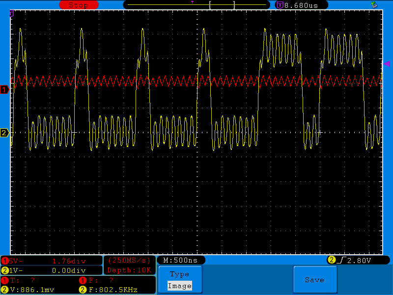
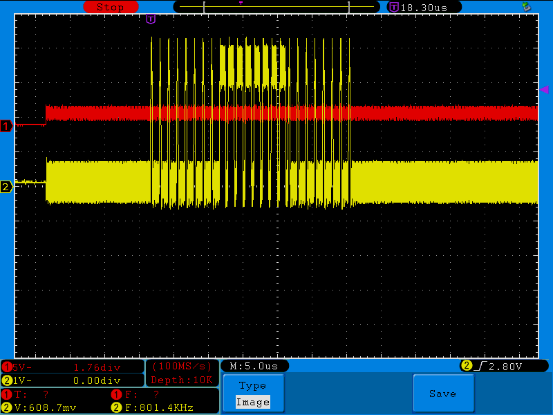
Using the "capture to file" feature of my DSO (thanks again E14, it's really a nice one), and a bit of editing in Paint.Net, I'm getting the following trace on the output pin:

image

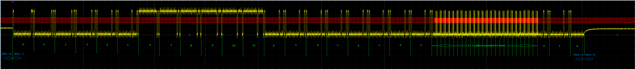
So, the 8 queued samples are sent just fine, then an additional 4 as well, but after that, the subsystem keeps repeating samples 4 and 5 until I turn off the TX channels, for no reasons that are obvious to me.

I understand that the subsystem will repeat the last sample it has received if I'm not providing new samples fast enough, but I'm sure they are all placed in the FIFO as the while loops exit. And why repeat #4 and #5 when clearly 6 others have been given (and sent) afterwards?

In the Audio subsystem example provided in the MSDK, they are using the interrupt vector which I'll try using over the week-end to see if it helps.

In the meantime, does this situation sound familiar to any of you? Would you have any recommendation?

Thanks in advance

  • Sign in to reply
  • Cancel

Top Replies

  • shabaz
    shabaz 5 days ago +1
    I think it's probably normal that 8 bits are dropped per 32 bits and set to zero in the I2S stream, if the DAC is only a 24-bit part. I've not checked the I2S spec in a while so I could be wrong. For a…
  • obones
    obones 15 hours ago +1
    Well, after lots of fiddling with code, I managed to get what I want: These are timings for 26 samples sent via I2S And pushing even further, I was finally able to address all 64 LEDs with a nice…
  • shabaz
    shabaz 5 days ago

    I think it's probably normal that 8 bits are dropped per 32 bits and set to zero in the I2S stream, if the DAC is only a 24-bit part. I've not checked the I2S spec in a while so I could be wrong. For a lot of scenarios it can be acceptable that one byte out of four is wasted, since it means easier processing on 4-byte boundaries - i.e. in the scenarios that memory isn't a concern, I wouldn't worry about the 25% waste.

    However, you mention not wanting to use all pins, of which normally at least several are required for the DAC to understand the data stream pin, so I'm wondering if there is some reason you wish the stream not to output zero.. are you trying to use the I2S functionality for some other purpose other than interfacing an I2S DAC? What's the use-case and what are you planning to interface (just in case there's some alternative solution).

    • Cancel
    • Vote Up +1 Vote Down
    • Sign in to reply
    • Cancel
  • obones
    obones 5 days ago in reply to shabaz

    Yes, I understand that most I2S devices only understand up to 24 bits per sample, but the datasheet clearly says it supports 32bits word size (table 23-3)

    I don't need all pins as I'm only using it to output, not capture any signal, so I thought that I could leave the DIN port in its default state (ie GPIO). But my experiments show that it MUST be configured as Alternate Function 1 for everything to work properly...

    And yes, I'm trying to use this to output an arbitrary long bit sequence which base frequency is the system frequency divided by twelve. And because the divider is not a power of two, that's the only subsystem that I could find that offers to do such a division (Section 23.4.2). From what I read, the SPI subsystem cannot do that for instance.

    • Cancel
    • Vote Up 0 Vote Down
    • Sign in to reply
    • Cancel
  • shabaz
    shabaz 5 days ago in reply to obones

    It may be either a bug in whatever config/API code you're using, or somewhere else that 32-bit DAC also needs to be configured too. I doubt many people tested 32-bit since most DACs will probably be 16 or 24-bit, so perhaps it's a bug in their code (i.e. might need registers examining in the datasheet and perhaps configuring it manually). 

    What's the actual goal, what equipment needs that bit sequence, and what is that frequency? 

    • Cancel
    • Vote Up 0 Vote Down
    • Sign in to reply
    • Cancel
  • jc2048
    jc2048 4 days ago

    Is it possibly down to all the printf debug statements wasting too much time so it can't keep up?

    • Cancel
    • Vote Up 0 Vote Down
    • Sign in to reply
    • Cancel
  • obones
    obones 4 days ago in reply to jc2048

    I thought that too, but they weren't there in the loop when I did the capture above. I only added them to try to figure out what's going on, and it did not change the result.
    Here is the output with the printf:

    wordIndex before saturate: 0
    int_pcm_tx_status: 00000000'00000000'00000000'00000000
    wordIndex after saturate: 8
    int_pcm_tx_status: 11000000'00000000'00000000'00000000
    8 8 8 8 8 8 8 8 12
    wordIndex at end: 26
    int_pcm_tx_status: 00000000'00000000'00000000'00000000

    I see that it waits for a while with the buffer full, puts 4 more samples, and then no longer waits in the while loop until everything is "written" in the FIFO buffers.

    • Cancel
    • Vote Up 0 Vote Down
    • Sign in to reply
    • Cancel
  • jc2048
    jc2048 4 days ago

    The datasheet says sample rates up to 192k. That's a bit clock of 12.288MHz with frames of 32 bits. Period 81ns. Are you trying to work faster to drive your LEDs? Although you may be able to program the clock to do that, there's no guarantee the data handling and framing will play ball. I'd start with 192k, and get that working first, before trying to stretch it beyond what it was designed for.

    • Cancel
    • Vote Up 0 Vote Down
    • Sign in to reply
    • Cancel
  • obones
    obones 3 days ago in reply to shabaz

    The datasheet does not say much more than "32 bits words are supported".

    The end goal is to generate a bit sequence suitable for WS281B LEDs inside the FastLED library. But it could also be outside FastLED, I'm just trying to generate the proper sequence.
    Thing is, bit banging cannot work, the fastest I can turn on / turn off a single pin is 600ns for a complete cycle. And that's without any code between the two pin set instructions.
    I thought about using the pulse train engine, but that's not desirable as it gets output on pins that are not routed on that board

    Hence the reason I'm trying to use the Audio subsystem with a clock set at 8MHz, and it seems that I can get the proper signal, provided I make sure the read/write of samples happens quite fast:

    image

    The 1250ns per byte are there, with the expected Ton for 0 or 1 so that should work.

    Well, I say should because it seems the 900mV that appear on the line before the bits are output is interfering with the level shifter that I'm using, the same one that works fine with an ESP32.

    I updated the code at Github, on to chase a way to get rid of that 900mV and see if it helps

    Thanks for the replies

    • Cancel
    • Vote Up 0 Vote Down
    • Sign in to reply
    • Cancel
  • shanewrn
    shanewrn 16 hours ago

    it reminded me of times I’ve chased weird timing issues on microcontrollers. The way the MAX32666 repeats samples feels like one of those cases where the hardware only behaves if every setting lines up just right. I’ve run into similar FIFO and sync problems before, so it was interesting to see the same kind of troubleshooting play out and it actually gave me a couple ideas for my own projects.

    • Cancel
    • Vote Up 0 Vote Down
    • Sign in to reply
    • Cancel
  • obones
    obones 15 hours ago in reply to shanewrn

    Yeah, that's likely an issue here. After experimenting a bit more, even if it's not specified in the datasheet, it seems the FIFOs are implemented as ring buffers. This means that if the write pointer is no longer updated, the read pointer will eventually catch up to it and stop being updated as well, being stuck on the sample_count - buffer_size value, not the last one as the wording in the datasheet implies. That means I had to make sure there are enough "all zero" samples set in the buffers to make sure to get a final low level.

    • Cancel
    • Vote Up 0 Vote Down
    • Sign in to reply
    • Cancel
  • obones
    obones 15 hours ago

    Well, after lots of fiddling with code, I managed to get what I want:

    image

    These are timings for 26 samples sent via I2S

    And pushing even further, I was finally able to address all 64 LEDs with a nice repeating pattern:

    image

    With the first hurdle out of the way, let's move on to the next ones: BMI160, SDHC, BTLE...

    I'm not sure I will manage to get everything working, but if wouldn't be a challenge if there wasn't some hair pulling involved.

    Thanks for all the recommendation

    • Cancel
    • Vote Up +1 Vote Down
    • Sign in to reply
    • Cancel
element14 Community

element14 is the first online community specifically for engineers. Connect with your peers and get expert answers to your questions.

  • Members
  • Learn
  • Technologies
  • Challenges & Projects
  • Products
  • Store
  • About Us
  • Feedback & Support
  • FAQs
  • Terms of Use
  • Privacy Policy
  • Legal and Copyright Notices
  • Sitemap
  • Cookies

An Avnet Company © 2025 Premier Farnell Limited. All Rights Reserved.

Premier Farnell Ltd, registered in England and Wales (no 00876412), registered office: Farnell House, Forge Lane, Leeds LS12 2NE.

ICP 备案号 10220084.

Follow element14

  • X
  • Facebook
  • linkedin
  • YouTube