element14 Community
element14 Community
    Register Log In
  • Site
  • Search
  • Log In Register
  • About Us
  • Community Hub
    Community Hub
    • What's New on element14
    • Feedback and Support
    • Benefits of Membership
    • Personal Blogs
    • Members Area
    • Achievement Levels
  • Learn
    Learn
    • Ask an Expert
    • eBooks
    • element14 presents
    • Learning Center
    • Tech Spotlight
    • STEM Academy
    • Webinars, Training and Events
    • Learning Groups
  • Technologies
    Technologies
    • 3D Printing
    • FPGA
    • Industrial Automation
    • Internet of Things
    • Power & Energy
    • Sensors
    • Technology Groups
  • Challenges & Projects
    Challenges & Projects
    • Design Challenges
    • element14 presents Projects
    • Project14
    • Arduino Projects
    • Raspberry Pi Projects
    • Project Groups
  • Products
    Products
    • Arduino
    • Avnet Boards Community
    • Dev Tools
    • Manufacturers
    • Multicomp Pro
    • Product Groups
    • Raspberry Pi
    • RoadTests & Reviews
  • Store
    Store
    • Visit Your Store
    • Choose another store...
      • Europe
      •  Austria (German)
      •  Belgium (Dutch, French)
      •  Bulgaria (Bulgarian)
      •  Czech Republic (Czech)
      •  Denmark (Danish)
      •  Estonia (Estonian)
      •  Finland (Finnish)
      •  France (French)
      •  Germany (German)
      •  Hungary (Hungarian)
      •  Ireland
      •  Israel
      •  Italy (Italian)
      •  Latvia (Latvian)
      •  
      •  Lithuania (Lithuanian)
      •  Netherlands (Dutch)
      •  Norway (Norwegian)
      •  Poland (Polish)
      •  Portugal (Portuguese)
      •  Romania (Romanian)
      •  Russia (Russian)
      •  Slovakia (Slovak)
      •  Slovenia (Slovenian)
      •  Spain (Spanish)
      •  Sweden (Swedish)
      •  Switzerland(German, French)
      •  Turkey (Turkish)
      •  United Kingdom
      • Asia Pacific
      •  Australia
      •  China
      •  Hong Kong
      •  India
      •  Korea (Korean)
      •  Malaysia
      •  New Zealand
      •  Philippines
      •  Singapore
      •  Taiwan
      •  Thailand (Thai)
      • Americas
      •  Brazil (Portuguese)
      •  Canada
      •  Mexico (Spanish)
      •  United States
      Can't find the country/region you're looking for? Visit our export site or find a local distributor.
  • Translate
  • Profile
  • Settings
Embedded and Microcontrollers
  • Technologies
  • More
Embedded and Microcontrollers
Pic Microcontrollers Forum PIC10F microcontroller output pin tolerance to overriding voltages
  • Blog
  • Forum
  • Documents
  • Quiz
  • Polls
  • Files
  • Members
  • Mentions
  • Sub-Groups
  • Tags
  • More
  • Cancel
  • New
Join Embedded and Microcontrollers to participate - click to join for free!
Actions
  • Share
  • More
  • Cancel
Forum Thread Details
  • State Not Answered
  • Replies 8 replies
  • Subscribers 190 subscribers
  • Views 1354 views
  • Users 0 members are here
Related

PIC10F microcontroller output pin tolerance to overriding voltages

davebullockmbe
davebullockmbe over 1 year ago

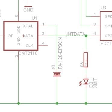
I am using PIC10F microcontrollers in a wireless project that has evolved into needing to use an 'in circuit' programmable radio IC.

The problem is that the GP2 pin of the PIC would be connected to the DATA input (and programming) pin3 of the radio IC.
The whole circuit is running off 3v7 lipo battery.
My question is will the PIC GP2 output be destroyed when programming the radio IC. ?

Thanks in anticipation....

Daveimage

  • Sign in to reply
  • Cancel

Top Replies

  • michaelkellett
    michaelkellett over 1 year ago in reply to davebullockmbe +2
    You can set GP2 as an input to prevent it from loading the radio pin during programming: From the Microchip data sheet. 5.2 TRIS Registers The Output Driver Control register is loaded with the contents…
Parents
  • scottiebabe
    0 scottiebabe over 1 year ago

    If you could hold the processor in reset, GP2 would be tri-stated...

    • Cancel
    • Vote Up 0 Vote Down
    • Sign in to reply
    • Verify Answer
    • Cancel
  • davebullockmbe
    0 davebullockmbe over 1 year ago in reply to scottiebabe

    Yes the problem with adding a diode in series with the data line is as you say the data pin of the radio chip will float and so need a resistor to pull it down. Unlike Microchip datasheets I cannot find any information about the internal structure of these radio IC's ie. whether they have internal pull-ups/downs. I have just about run out of board space and am struggling to add even one more component.
    However putting the PIC10F202 into reset would be a great idea but doesn't this need extra PIC code to force the o/p pins into tristate. I don't think toggling MCLR does this on it's own?
    Dave

    • Cancel
    • Vote Up 0 Vote Down
    • Sign in to reply
    • Verify Answer
    • Cancel
  • michaelkellett
    0 michaelkellett over 1 year ago in reply to davebullockmbe

    You can set GP2 as an input to prevent it from loading the radio pin during programming:

    From the Microchip data sheet.

    5.2 TRIS Registers
    The Output Driver Control register is loaded with the
    contents of the W register by executing the TRIS f
    instruction. A ‘1’ from a TRIS register bit puts the corresponding
    output driver in a High-impedance mode. A
    ‘0’ puts the contents of the output data latch on the
    selected pins, enabling the output buffer. The exceptions
    are GP3, which is input only and the GP2/T0CKI/
    COUT/FOSC4 pin, which may be controlled by various
    registers. See Table 5-1

    MK

    • Cancel
    • Vote Up +2 Vote Down
    • Sign in to reply
    • Verify Answer
    • Cancel
Reply
  • michaelkellett
    0 michaelkellett over 1 year ago in reply to davebullockmbe

    You can set GP2 as an input to prevent it from loading the radio pin during programming:

    From the Microchip data sheet.

    5.2 TRIS Registers
    The Output Driver Control register is loaded with the
    contents of the W register by executing the TRIS f
    instruction. A ‘1’ from a TRIS register bit puts the corresponding
    output driver in a High-impedance mode. A
    ‘0’ puts the contents of the output data latch on the
    selected pins, enabling the output buffer. The exceptions
    are GP3, which is input only and the GP2/T0CKI/
    COUT/FOSC4 pin, which may be controlled by various
    registers. See Table 5-1

    MK

    • Cancel
    • Vote Up +2 Vote Down
    • Sign in to reply
    • Verify Answer
    • Cancel
Children
No Data
element14 Community

element14 is the first online community specifically for engineers. Connect with your peers and get expert answers to your questions.

  • Members
  • Learn
  • Technologies
  • Challenges & Projects
  • Products
  • Store
  • About Us
  • Feedback & Support
  • FAQs
  • Terms of Use
  • Privacy Policy
  • Legal and Copyright Notices
  • Sitemap
  • Cookies

An Avnet Company © 2025 Premier Farnell Limited. All Rights Reserved.

Premier Farnell Ltd, registered in England and Wales (no 00876412), registered office: Farnell House, Forge Lane, Leeds LS12 2NE.

ICP 备案号 10220084.

Follow element14

  • X
  • Facebook
  • linkedin
  • YouTube