element14 Community
element14 Community
    Register Log In
  • Site
  • Search
  • Log In Register
  • Community Hub
    Community Hub
    • What's New on element14
    • Feedback and Support
    • Benefits of Membership
    • Personal Blogs
    • Members Area
    • Achievement Levels
  • Learn
    Learn
    • Ask an Expert
    • eBooks
    • element14 presents
    • Learning Center
    • Tech Spotlight
    • STEM Academy
    • Webinars, Training and Events
    • Learning Groups
  • Technologies
    Technologies
    • 3D Printing
    • FPGA
    • Industrial Automation
    • Internet of Things
    • Power & Energy
    • Sensors
    • Technology Groups
  • Challenges & Projects
    Challenges & Projects
    • Design Challenges
    • element14 presents Projects
    • Project14
    • Arduino Projects
    • Raspberry Pi Projects
    • Project Groups
  • Products
    Products
    • Arduino
    • Avnet & Tria Boards Community
    • Dev Tools
    • Manufacturers
    • Multicomp Pro
    • Product Groups
    • Raspberry Pi
    • RoadTests & Reviews
  • About Us
    About the element14 Community
  • Store
    Store
    • Visit Your Store
    • Choose another store...
      • Europe
      •  Austria (German)
      •  Belgium (Dutch, French)
      •  Bulgaria (Bulgarian)
      •  Czech Republic (Czech)
      •  Denmark (Danish)
      •  Estonia (Estonian)
      •  Finland (Finnish)
      •  France (French)
      •  Germany (German)
      •  Hungary (Hungarian)
      •  Ireland
      •  Israel
      •  Italy (Italian)
      •  Latvia (Latvian)
      •  
      •  Lithuania (Lithuanian)
      •  Netherlands (Dutch)
      •  Norway (Norwegian)
      •  Poland (Polish)
      •  Portugal (Portuguese)
      •  Romania (Romanian)
      •  Russia (Russian)
      •  Slovakia (Slovak)
      •  Slovenia (Slovenian)
      •  Spain (Spanish)
      •  Sweden (Swedish)
      •  Switzerland(German, French)
      •  Turkey (Turkish)
      •  United Kingdom
      • Asia Pacific
      •  Australia
      •  China
      •  Hong Kong
      •  India
      •  Japan
      •  Korea (Korean)
      •  Malaysia
      •  New Zealand
      •  Philippines
      •  Singapore
      •  Taiwan
      •  Thailand (Thai)
      •  Vietnam
      • Americas
      •  Brazil (Portuguese)
      •  Canada
      •  Mexico (Spanish)
      •  United States
      Can't find the country/region you're looking for? Visit our export site or find a local distributor.
  • Translate
  • Profile
  • Settings
Experts, Learning and Guidance
  • Technologies
  • More
Experts, Learning and Guidance
Ask an Expert Forum mic29502wt
  • Blog
  • Forum
  • Documents
  • Leaderboard
  • Files
  • Members
  • Mentions
  • Sub-Groups
  • Tags
  • More
  • Cancel
  • New
Join Experts, Learning and Guidance to participate - click to join for free!
Actions
  • Share
  • More
  • Cancel
Forum Thread Details
  • State Suggested Answer
  • Replies 21 replies
  • Answers 3 answers
  • Subscribers 340 subscribers
  • Views 3731 views
  • Users 0 members are here
  • help
Related
See a helpful answer?

Be sure to click 'more' and select 'suggest as answer'!

If you're the thread creator, be sure to click 'more' then 'Verify as Answer'!

mic29502wt

skal
skal over 10 years ago

Hi


i don't really know much about this device ,but i would like to use it in a regulated vacuum tube filament supply  , output voltage should be able to move from min voltage to about 10vdc ,6.3v @ 3A max load.


I have played with the lm317 and the 5A version  to that device and i could never get them to regulated properly and  they very easy to damage , 


My luck with SS parts , are a joke maybe it is ,the lack of knowledge in this area , which is stopping me from understanding how these reg work and @ £ 7 a pop i need to be pretty sure

about what resistors and capacitors are needed for the project before i  buy  a single Ldo


cheers

  • Sign in to reply
  • Cancel

Top Replies

  • shabaz
    shabaz over 10 years ago in reply to skal +1
    So you're paralleling up valve filaments.. I'm guessing the adjustable nature is so that it is possible to control the precise current through the filament? If so then an adjustable supply is not much…
  • mudz
    0 mudz over 10 years ago in reply to skal

    Hi, I have not read the whole discussion but If you are really considering to blow up something(which is a fun thing to do) you might wanna add Peltier cooler on heatsink or directly on it. Who knows if Peltier fails, it will heat that thing up more and it can be really a fun thing to watch that piece giving beautiful color of smoke.


    mudz

    • Cancel
    • Vote Up 0 Vote Down
    • Sign in to reply
    • Verify Answer
    • Cancel
  • skal
    0 skal over 10 years ago in reply to mudz

    No i need 6.3vdc @ 3A shabaz J


    Ok this is what i am thinking  6.3 Vac @10A TRANSFORMER  INPUT  TO BRIDGE=  8.883Vd.c and current=6.2Ad.c ok


    if this is correct i need a 2.2vdc drop over a resistor at 6.2Ad.c (2.2vdc 6.2Ad.c)R=0.354  Watts=14 i could use 2 resistors to half the wattage less heat after rectification i will filter with 2* 10000uf  to reg .


    ok now to program the output voltage

    Vout = 1.24(1 + [R1 + VR1] / R2)

    so this is the bit that  i can not grasp the above formula


    regards


    den

    • Cancel
    • Vote Up 0 Vote Down
    • Sign in to reply
    • Verify Answer
    • Cancel
  • shabaz
    0 shabaz over 10 years ago in reply to skal

    I don't understand why there is a resistor, it doesn't gain you anything - you now have two devices that are dissipating the same total amount of power.

    Also, it now sounds like you are designing an entire AC power supply, not just connecting your Linear regulator to a filament. This would need a lot more thinking - for a start 2 x 10,000uF is too low since you can't afford to have too much ripple if you're running your linear regulator with a voltage close to the dropout voltage. You might need to double it. I've not checked any of your figures but I also didn't understand where the 6.2A came from.

    Anyway if your 14W figure is correct, which it could be, then this needs a big heatsink. May I ask what this is all needed for?

    If it is for a valve/tube, the filament might not need a DC supply. I know nothing about them (is this what it is required for?) but as I understand AC is quite common, since the heater/filament just needs to be hot.

    If you want a regulated supply, it would be easier (and safer) to get an off-the-shelf one - they even come in chassis mount variants, and are efficient if you use a switched-mode one. 7V ones are available, which could just have a 2W resistor (and maybe a thermistor in series too) connected to the filament. This XP Power oneThis XP Power one probably costs less than the parts to build one (external ones are cheaper still).


    Also, where was 3A derived from, is that an estimate or you know for sure this is what is needed? Because that would drive a lot of valve/tube filaments - my only book on the topic says that current requirement is 0.1 to 0.3A for a range of typical valve filaments.

    (My apologies if you have already considered all these points. I have no idea if you have, hence the reason I'm asking to confirm that you have considered them).

    Regarding the formula, you can choose to have either R1 or R2 fixed, and you choose any value for it. There may be restrictions in the datasheet, e.g. R2 to be between x ohms and y ohms. Once you have picked a value for it, you can see what Vout will be for various values or the other resistor. Pick a variable resistor with that range. For example if you need between 1kohm and 11kohm to adjust between 6V and 10V, then your resistor can be a 10k variable resistor in series with a 1k resistor. This is not dissimilar to the way you must have used the LM317, just the formula may be different but it is the same format.

    • Cancel
    • Vote Up 0 Vote Down
    • Sign in to reply
    • Verify Answer
    • Cancel
  • skal
    0 skal over 10 years ago in reply to shabaz

    I think i should clarify the the project at this moment.


    1) regulated 6.3vdc

    2) should be able to supply current of  2.4A-3A  (0.300*8)=2.4A

    3) the lowest low ripple i can achieve from reg


    where the 6.2A came fromshabaz Jan 28, 2016 4:28 AM


    its the max current the tx can deliver after rectification at  8.883Vd.c i think, correct me if i am wrong


    Is this for a valve/tube filament, yes


    I think 5.5v to 7v would be a good place for the adjustment range


    regards

    • Cancel
    • Vote Up 0 Vote Down
    • Sign in to reply
    • Verify Answer
    • Cancel
  • shabaz
    0 shabaz over 10 years ago in reply to skal

    So you're paralleling up valve filaments.. I'm guessing the adjustable nature is so that it is possible to control the precise current through the filament? If so then an adjustable supply is not much use for this since the same voltage will be applied to all of them and there is no granular control since there could be variations of filament resistance - you may as well use a fixed supply.


    Rather that all this complication, better to go for the fixed 7V supply such as the XP Power one (off-the-shelf, safe, efficient, far less heat dissipation issues).

    Then stick a 0.5W fixed resistor (and maybe thermistor - your decision) in series with each filament. You therefore get precise control per filament - use a wirewound potentiometer to do any trimming if this is what you really want (I have no idea), before you replace with a fixed resistor - and it is completely regulated, and it protects your filaments. All advantages.

    • Cancel
    • Vote Up +1 Vote Down
    • Sign in to reply
    • Verify Answer
    • Cancel
  • jc2048
    0 jc2048 over 10 years ago

    If you are managing to blow up LM137s you need to be very cautious before using the MIC29502 If it were me I'd try and understand why the LM317s were dying before doing anything else(Are you sure you are killing them They have an internal temperature monitor and will shut down and refuse to operate if they get too hot Most LM317s are rated at 1.5A for normal use the current limit will be higher than that but you don't know exactly where it will cut in and you don't want to be operating close under it


    Given how cheap the LM317s are compared to the MIC29502 couldn't you use a pair of them with each one running 4 filaments(4 x 300mA 1.2A[For the cost of the MIC29502 you could give each filament its own LM317


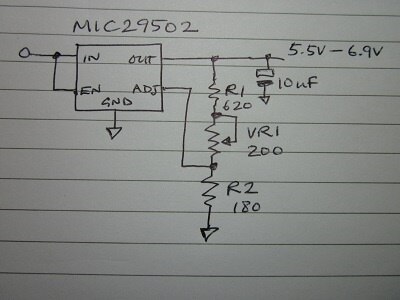
    If you do want to try a MIC29502, here's how it would look


    image


    The calculation of the resistors works differently to the LM317. The LM317 is a floating regulator and its control loop compares the voltage between the ADJ pin and the output pin with the internal reference to control the pass element (the internal transistor that adjusts the current to the output). The MIC29502 is ground referenced and is comparing the voltage at the ADJ pin relative to GND with the reference voltage.


    Here's how I got the values on the drawing.


    I started with the potentiometer. They come in far fewer different values than fixed resistors, typically in a 1,2,5 sequence. You wanted an adjustment range of about 1.5V. A 200 ohm pot seemed like a good start. With 1.5V across it, that would mean a current of 1.5/200 = 7.5mA (the current flows from the output down through R1, VR1, and R2 to ground) which is reasonable. The regulator tries to hold the ADJ pin at 1.24V, so resistor R2 would be 1.24V/7.5mA = 165 ohms. Here we have a choice - 150 and 180 are standard values - and I chose 180 ohms; that compromises your adjustment range a little but I reckoned it would still be acceptable (you can rework the values if it's not). Now the current isn't 7.5mA any longer, instead the regulator will maintain a current of 1.24V / 180ohms = 6.88mA which I'll use for the rest of the calculations. We have two of the values, we just need a value for R1. Let's say we have the pot at the halfway point.  The resistance will be 100 ohms. We want that to correspond to 6.3V. The total resistance (R1+VR1+R2) is 6.3V / 6.88mA = 916 ohms. So, R1 = 916 - (180 + 100) = 636 ohms. Nearest value is 620.


    With the pot set to zero, the output voltage will be 5.5V.


    With the pot set to 200ohms, the output will be 6.88V.


    If you want to check that I've got it right, take the output voltages above and the R2 value and plug them into the formula on the datasheet and see what value it comes up with for R1 in each case. If it matches R1 + VR1 then we're there.


    One additional thing to note is that the part has a minimum current of 10mA and the current I've chosen is less than that. It won't matter once you get your filaments connected, but if you want to test it first before you connect them put a small load on the output (1K will do) otherwise it may not regulate properly. Alternatively you could scale all the resistor values so that the current through the chain is more than the 10mA.


    Couple of other observations


    1/ don't forget the diode drops in the bridge when calculating the transformer voltage you'll need (2 x 0.9V = 1.8V at 3A)


    2/ the ripple on 20000uF at 50Hz is about 1.5V at 3A and 1.2V at 2.4A

    • Cancel
    • Vote Up 0 Vote Down
    • Sign in to reply
    • Verify Answer
    • Reject Answer
    • Cancel
  • skal
    0 skal over 10 years ago in reply to jc2048

    Thank you ,this is what i needed the method of working out the values, i can go away now and plugin some values to see what i get..


    cheers


    Den

    • Cancel
    • Vote Up 0 Vote Down
    • Sign in to reply
    • Verify Answer
    • Cancel
  • skal
    0 skal over 10 years ago in reply to skal

    i was also looking at these diodes for the rectification stage (SB540-E3/54 - VISHAY - Rectifier Diode, Single, 40 V, 5 A, DO-201AD, 2, 480 mV | Farnell element14  ), should the job, times 4 and 3 times 27000uf two filtering the ac ripple  and one after the reg. (http://uk.farnell.com/multicomp/mchpr16v279m30x31/cap-alu-elec-27000uf-16v-snap/dp/1903174 )


    do think these should do the job.


    Den

    • Cancel
    • Vote Up 0 Vote Down
    • Sign in to reply
    • Verify Answer
    • Cancel
  • michaelkellett
    0 michaelkellett over 10 years ago in reply to skal

    You might do better using a ready built bridge rectifier rather than 4 diodes - I like this style because they are easy to heat sink and attach thick wires - this was the cheapest I found quickly at Farnell  CM1508 - MULTICOMP - Bridge Rectifier Diode, Single, 800 V, 15 A, 1.2 V, 4 | Farnell element14 if you want you can get a pcb mounting part even more cheaply. In fact they are so cheap you can easily afford to over specify on current and voltage which will make you design more robust.

    There is no point in putting a huge capacitor after the regulator - the values in the data sheet will be sufficient - and it cautions you against using  a very low ESR part so don't stick a big ceramic in ! 47uF should be OK. The output impedance of the regulator will be of the order of 0.01ohms up to a few hundred Hz (check the graphs on the data sheet) so putting  big cap there won't help. (At 100Hz you need 159,000 uF to get down to 0.01R !!).

    The type of capacitors you've chosen should be OK (did you mean them to be pcb mounted ?).


    MK

    • Cancel
    • Vote Up 0 Vote Down
    • Sign in to reply
    • Verify Answer
    • Reject Answer
    • Cancel
  • skal
    0 skal over 10 years ago in reply to michaelkellett

    yes i need pcb mounted capacitor , do i need a bleeder resistors for the capacitors,and   also is there any need for a 0.1uf film in the input and out of the reg , i have used them before with the lm317reg.


    cheers


    Den

    • Cancel
    • Vote Up 0 Vote Down
    • Sign in to reply
    • Verify Answer
    • Cancel
<>
element14 Community

element14 is the first online community specifically for engineers. Connect with your peers and get expert answers to your questions.

  • Members
  • Learn
  • Technologies
  • Challenges & Projects
  • Products
  • Store
  • About Us
  • Feedback & Support
  • FAQs
  • Terms of Use
  • Privacy Policy
  • Legal and Copyright Notices
  • Sitemap
  • Cookies

An Avnet Company © 2026 Premier Farnell Limited. All Rights Reserved.

Premier Farnell Ltd, registered in England and Wales (no 00876412), registered office: Farnell House, Forge Lane, Leeds LS12 2NE.

Follow element14

  • X
  • Facebook
  • linkedin
  • YouTube