element14 Community
element14 Community
    Register Log In
  • Site
  • Search
  • Log In Register
  • Community Hub
    Community Hub
    • What's New on element14
    • Feedback and Support
    • Benefits of Membership
    • Personal Blogs
    • Members Area
    • Achievement Levels
  • Learn
    Learn
    • Ask an Expert
    • eBooks
    • element14 presents
    • Learning Center
    • Tech Spotlight
    • STEM Academy
    • Webinars, Training and Events
    • Learning Groups
  • Technologies
    Technologies
    • 3D Printing
    • FPGA
    • Industrial Automation
    • Internet of Things
    • Power & Energy
    • Sensors
    • Technology Groups
  • Challenges & Projects
    Challenges & Projects
    • Design Challenges
    • element14 presents Projects
    • Project14
    • Arduino Projects
    • Raspberry Pi Projects
    • Project Groups
  • Products
    Products
    • Arduino
    • Avnet & Tria Boards Community
    • Dev Tools
    • Manufacturers
    • Multicomp Pro
    • Product Groups
    • Raspberry Pi
    • RoadTests & Reviews
  • About Us
  • Store
    Store
    • Visit Your Store
    • Choose another store...
      • Europe
      •  Austria (German)
      •  Belgium (Dutch, French)
      •  Bulgaria (Bulgarian)
      •  Czech Republic (Czech)
      •  Denmark (Danish)
      •  Estonia (Estonian)
      •  Finland (Finnish)
      •  France (French)
      •  Germany (German)
      •  Hungary (Hungarian)
      •  Ireland
      •  Israel
      •  Italy (Italian)
      •  Latvia (Latvian)
      •  
      •  Lithuania (Lithuanian)
      •  Netherlands (Dutch)
      •  Norway (Norwegian)
      •  Poland (Polish)
      •  Portugal (Portuguese)
      •  Romania (Romanian)
      •  Russia (Russian)
      •  Slovakia (Slovak)
      •  Slovenia (Slovenian)
      •  Spain (Spanish)
      •  Sweden (Swedish)
      •  Switzerland(German, French)
      •  Turkey (Turkish)
      •  United Kingdom
      • Asia Pacific
      •  Australia
      •  China
      •  Hong Kong
      •  India
      • Japan
      •  Korea (Korean)
      •  Malaysia
      •  New Zealand
      •  Philippines
      •  Singapore
      •  Taiwan
      •  Thailand (Thai)
      • Vietnam
      • Americas
      •  Brazil (Portuguese)
      •  Canada
      •  Mexico (Spanish)
      •  United States
      Can't find the country/region you're looking for? Visit our export site or find a local distributor.
  • Translate
  • Profile
  • Settings
Experts, Learning and Guidance
  • Technologies
  • More
Experts, Learning and Guidance
Ask an Expert Forum Beginner here. Designed a PC Arcade Controller, trying to figure out how to make it work.
  • Blog
  • Forum
  • Documents
  • Leaderboard
  • Files
  • Members
  • Mentions
  • Sub-Groups
  • Tags
  • More
  • Cancel
  • New
Join Experts, Learning and Guidance to participate - click to join for free!
Actions
  • Share
  • More
  • Cancel
Forum Thread Details
  • State Suggested Answer
  • Replies 26 replies
  • Answers 10 answers
  • Subscribers 305 subscribers
  • Views 4420 views
  • Users 0 members are here
  • custom arcade stick
  • teensy
Related
See a helpful answer?

Be sure to click 'more' and select 'suggest as answer'!

If you're the thread creator, be sure to click 'more' then 'Verify as Answer'!

Beginner here. Designed a PC Arcade Controller, trying to figure out how to make it work.

lyndan
lyndan over 8 years ago

Over the past month or so I've been working on a design for my ideal PC game controller and I'm getting closer to figuring it all out.. And I was wondering if I could run it by the experts here for some help in understanding it all.

Here is the latest version of my design!

image


It started as my ideal handheld controller and evolved into an arcade stick. The stick I plan to build has two analog sticks; the leftmost analog stick being Ultimarc's Ultrastik 360 (or U360) and the rightmost being a thumbstick. Also on my design are 12 pushbuttons.

So I've been doing a lot of searching and learning about interfaces and such, but I still feel very in the dark. At this point, I believe it's a Teensy board that I'll need in order to convert these signals to digital so my PC can recognize my arcade controller as a HID. So as far as I understand, the voltage of the Interface I use will need to support the highest voltage of any of my switches, right? The U360 has it's own interface that you can hook to buttons and plug and play, but it only supports eight buttons, and my project incorporates 12 plus an additional analog stick. The U360 can also work in output mode, with 2 of it's eight pins outputting raw analog signal. Also note the stick can output digital 100% signals, but that is not what I want to use. I need the analog signals.

Here's the info on the U360: http://www.ultimarc.com/ultrastik_inst.html

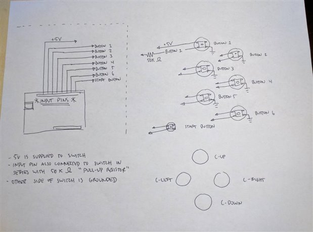
So it shows the pin for powering the U360 is 5V.

Sorry for getting off topic a bit, but it says on the raw analog signals "not used at present".. Does this mean I wouldn't be able to use it? I contacted Andy at Ultimarc and he said it can output raw analog, but he seemed to want me to also buy his I-PAC for my extra buttons, which doesn't support analog, and just make my project act as two separate devices: one for the ultrastick and one for the buttons. That still doesn't let me use my extra analog stick and is too... messy for what I want. I want it to be clean and simple.


Anyway, as far as I can understand, I'll need a Teensy board that can power 5V, connect the two raw analog pins of the U360 to the Teensy's analog inputs and it should work fine, right?

Here is the analog stick from Adafruit I plan to pair with it: https://www.adafruit.com/product/512  "Usable with any voltage up to 5V, 2 analog outputs. 1 milliamp draw when used with 5V"

So the two analog sticks would take up four analog pins on a board, right? Then all that's left are the buttons which I can't find the voltage for.. it doesn't say on any of the sites for ordering them. I guess that's not something you have to worry about?

With all this information, if you notice something I'm missing, please let me know.


I guess the main questions I'm asking are: is this going to work with this U360 analog stick wired to a Teensy board, and which board should I buy for this project?

Thank you so much for your time.

  • Sign in to reply
  • Cancel

Top Replies

  • jeremy.f.medlin
    jeremy.f.medlin over 8 years ago in reply to lyndan +2 suggested
    Maybe this will help. Arduino is on the left. Each one of those lines represents a wire going somewhere. That +5V which is your power rail will connect to one side of your switch. Then an input pin wire…
  • Sean_Miller
    Sean_Miller over 8 years ago +1 suggested
    Good discussion. Your thumbstick is probably just two mechanically driven potentiometers that center on Vcc/2. So, not counting power and ground, you will consume two pins per stick. Get you the prototyping…
  • jeremy.f.medlin
    jeremy.f.medlin over 8 years ago in reply to lyndan +1 suggested
    Ah okay! Yep, definitely a way to get the joystick info. Hall effect sensors use voltage to determine direction, so you would read the voltage at the pins in order to find the direction and distance the…
Parents
  • Sean_Miller
    0 Sean_Miller over 8 years ago

    Good discussion.  Your thumbstick is probably just two mechanically driven potentiometers that center on Vcc/2.  So, not counting power and ground, you will consume two pins per stick.


    Get you the prototyping rig (bread board, jumper (DuPont) cables, your switches/thumbsticks, and an Arduino) rocking and rolling and we'll go from there.  Once you achieve that, you might want to build an R2D2 instead.


    -Sean

    • Cancel
    • Vote Up +1 Vote Down
    • Sign in to reply
    • Verify Answer
    • Reject Answer
    • Cancel
  • lyndan
    0 lyndan over 8 years ago in reply to Sean_Miller

    I believe the thumbstick uses pots, but the U360 Joystick uses hall effect sensors with a magnet at the bottom of the joystick shaft.

    UltraStik1.jpg

    Still outputs an X and Y signal, so it should work the same way, right?

    Hahaa.. I'm not crazy about Star Wars, but I probably won't stop at building an arcade stick! image

    • Cancel
    • Vote Up 0 Vote Down
    • Sign in to reply
    • Verify Answer
    • Cancel
  • jeremy.f.medlin
    0 jeremy.f.medlin over 8 years ago in reply to lyndan

    Ah okay! Yep, definitely a way to get the joystick info. Hall effect sensors use voltage to determine direction, so you would read the voltage at the pins in order to find the direction and distance the joystick was pushed. Still should be fine using that with Arduino.


    The tricky bit will be once you prototype your board with the hardware, is figuring out how to handle the joystick information in the Arduino coding.


    I agree with Sean that you should go ahead and build the prototype because once everything is hooked up, the coding section is a whole other animal. Good idea to build it and get excited for it, then we'll tackle the software side image

    • Cancel
    • Vote Up +1 Vote Down
    • Sign in to reply
    • Verify Answer
    • Reject Answer
    • Cancel
  • jeremy.f.medlin
    0 jeremy.f.medlin over 8 years ago in reply to lyndan

    image

    Maybe this will help. Arduino is on the left. Each one of those lines represents a wire going somewhere. That +5V which is your power rail will connect to one side of your switch. Then an input pin wire will run from an Arduino pin to the switch in series with a 50K Ohm pull-up resistor. Also that little tail coming off the right bottom of the switch means its connected to ground. If you can see, that means that the 5V power line is connected directly to an input pin THROUGH your switch AND the 50K ohm resistor. This means that when your button is not pressed, the Arduino will "see" the button at 5V but as soon as you press the button the power line will be connected to your ground instead of your input pin and the voltage will drop to 0. Arduino will then see that 0V as a sign the button has been pressed.


    I hope this drawing isnt confusing, I only actually filled in how Button 1 will work, but the rest of the buttons will be wired and will work the exact same way. As for the joysticks, they will be a bit different so I figured we'll wait on those.

    • Cancel
    • Vote Up +2 Vote Down
    • Sign in to reply
    • Verify Answer
    • Reject Answer
    • Cancel
Reply
  • jeremy.f.medlin
    0 jeremy.f.medlin over 8 years ago in reply to lyndan

    image

    Maybe this will help. Arduino is on the left. Each one of those lines represents a wire going somewhere. That +5V which is your power rail will connect to one side of your switch. Then an input pin wire will run from an Arduino pin to the switch in series with a 50K Ohm pull-up resistor. Also that little tail coming off the right bottom of the switch means its connected to ground. If you can see, that means that the 5V power line is connected directly to an input pin THROUGH your switch AND the 50K ohm resistor. This means that when your button is not pressed, the Arduino will "see" the button at 5V but as soon as you press the button the power line will be connected to your ground instead of your input pin and the voltage will drop to 0. Arduino will then see that 0V as a sign the button has been pressed.


    I hope this drawing isnt confusing, I only actually filled in how Button 1 will work, but the rest of the buttons will be wired and will work the exact same way. As for the joysticks, they will be a bit different so I figured we'll wait on those.

    • Cancel
    • Vote Up +2 Vote Down
    • Sign in to reply
    • Verify Answer
    • Reject Answer
    • Cancel
Children
  • lyndan
    0 lyndan over 8 years ago in reply to jeremy.f.medlin

    Did you draw that just for me? :O

    I didn't even realize I would need resisitors. Going to go now to watch some videos to understand exactly what a pull-up resistor does and why I need it. Thank you so much!

    I'll get my hands on the parts soon and come back to update when I have something to show! Thank you all so much for your help!!

    image

    • Cancel
    • Vote Up 0 Vote Down
    • Sign in to reply
    • Verify Answer
    • Cancel
  • jeremy.f.medlin
    0 jeremy.f.medlin over 8 years ago in reply to lyndan

    Yep, just keep track of the things you don't understand and if videos aren't explaining things well ask them in this thread and I'll give it a try.

    • Cancel
    • Vote Up 0 Vote Down
    • Sign in to reply
    • Verify Answer
    • Cancel
  • beacon_dave
    0 beacon_dave over 8 years ago in reply to jeremy.f.medlin

    This drawing isn't right.


    A pull-up resistor input circuit looks like this:

    https://learn.sparkfun.com/tutorials/pull-up-resistors/what-is-a-pull-up-resistor


    There are pull-up resistors built into the Arduino MCU which could also be enabled in code.

    • Cancel
    • Vote Up +1 Vote Down
    • Sign in to reply
    • Verify Answer
    • Reject Answer
    • Cancel
  • jeremy.f.medlin
    0 jeremy.f.medlin over 8 years ago in reply to beacon_dave

    Whoops, yeah the resistor should be on +5V to switch, was drawing fast. Putting resistor on the input line rather than 5V would mean that you are getting proper voltage and low current to Arduino, but as soon as you press the button, you are shorting the power rail directly to ground. No bueno.


    So the change should be, the 50K Ohm resistor just goes on the 5V rail going to each switch. Sorry.

    • Cancel
    • Vote Up +1 Vote Down
    • Sign in to reply
    • Verify Answer
    • Cancel
  • lyndan
    0 lyndan over 8 years ago in reply to jeremy.f.medlin

    So I would only need one pull-up resistor on the rail that goes to all the pushbuttons? No need to have one for every button?

    Also, would I need something like that for the analog signals, or are they fine as is?

    • Cancel
    • Vote Up 0 Vote Down
    • Sign in to reply
    • Verify Answer
    • Cancel
  • beacon_dave
    0 beacon_dave over 8 years ago in reply to lyndan

    You need one pull-up resistor per digital input. There are pull-ups/downs built into the MCU which can be enabled in code. You don't need the pull-up resistors on the analogue inputs.


    Perhaps take a few minutes to look at these tutorials:

    Tutorial 02 for Arduino: Buttons, PWM, and Functions

    Tutorial 04 for Arduino: Analog Inputs

    • Cancel
    • Vote Up +1 Vote Down
    • Sign in to reply
    • Verify Answer
    • Reject Answer
    • Cancel
  • jeremy.f.medlin
    0 jeremy.f.medlin over 8 years ago in reply to lyndan

    Each button gets its own 5V line with 50K resistor. The article might be a little dense on why you use pull-up resistors but think about it this way.


    Imagine each pin is "listening for a voltage." "Quiet" is 0V and your cell phone ringing is "5V." It's easy to hear a beep when you are in a quiet environment, but as soon as you try to hear that beep in New York City, all of a sudden all those noises interfere with you hearing that beep, or you might hear other beeps that you think are your cell phone, when really it's another person's cell phone.


    Now imagine that all that noise from the city is all the random electrical fields that happen in your environment around your Arduino. Even though you can't feel it, there are fields surrounding you all the time. If you left a pin ungrounded or without using pull-up resistors that is called "floating" a pin and any currents that happen around your device might induce voltages that give the impression to your Arduino that there is a button being pressed, but really it's just electrical noise from another device causing that voltage.


    The pull-up resistor allows the line to ALWAYS be at 5V effectively drowning out all other electrical noise so you never have the environment causing voltage readings that confuse your Arduino. So why not connect the 5V line directly to the switch and then to the Arduino input pin you might ask?


    Well heres an easy equation for you. I=V\R

    Current (in Amps) equals voltage (in Volts) divided by resistance (in Ohms).


    If you have a 5V line with hardly any resistance, then you will see an amount of current flowing through that pin equal to the amount of current your power supply can produce. Not good seeing as your Arduino can only handle about 40mA per pin.


    Instead we put a 50,000 (50K) Ohm resistor to allow the voltage to remain 5V, but resist current flow to keep the amount of current flowing through our pin to a safe level. Lets rework our equation.


    Current(to our Arduino pin) = 5V (from our power rail) divided by 50,000 (our pull-up resistor amount)

    Current =0.001 mA


    MUCH better! This allows the pin to stay "high" at 5V, but only pass 0.001 mA of current. The less current we pass through our resistor, the less heat we generate.


    Then when we press the button, we are allowing the current to flow to ground rather than flow to the input pin which the Arduino then "sees" as 0V (because there is no more connection). By having the pull-up resistor on the 5V line to the switch, it also limits the amount of current flowing to ground since the 50K resistor is in series with ground.

    • Cancel
    • Vote Up +1 Vote Down
    • Sign in to reply
    • Verify Answer
    • Reject Answer
    • Cancel
  • lyndan
    0 lyndan over 8 years ago in reply to beacon_dave

    Thank you for the links!

    So since the Arduino has built-in pull-up through code, I can just supply 5V to the input, with the switch connecting it to GND, yes?

    Then in code I'll type INPUT_PULLUP to draw the 5V so the input is never floating.

    image

    So as far as I understand, with the Arduino Uno I'll just hook the 5V to each button and code in the pull up.

    • Cancel
    • Vote Up 0 Vote Down
    • Sign in to reply
    • Verify Answer
    • Cancel
  • beacon_dave
    0 beacon_dave over 8 years ago in reply to lyndan

    no. you have just created a short circuit there.


    remove the 5v to the input - just connect the switch to the input if using internal pull-ups.


    your code will be similar to:

       pinMode(2,INPUT_PULLUP);

    to enable an internal pull-up resistor on pin 2


    you can experiment with this virtually using Autodesk TinkerCAD circuits

    https://www.tinkercad.com/circuits

    • Cancel
    • Vote Up 0 Vote Down
    • Sign in to reply
    • Verify Answer
    • Cancel
  • lyndan
    0 lyndan over 8 years ago in reply to beacon_dave

    I thought it was a short circuit! I just didn't understand how the internal pull-up would work. So I don't even have to supply the voltage to the buttons? The voltage will run through the input?

    image

    • Cancel
    • Vote Up 0 Vote Down
    • Sign in to reply
    • Verify Answer
    • Cancel
element14 Community

element14 is the first online community specifically for engineers. Connect with your peers and get expert answers to your questions.

  • Members
  • Learn
  • Technologies
  • Challenges & Projects
  • Products
  • Store
  • About Us
  • Feedback & Support
  • FAQs
  • Terms of Use
  • Privacy Policy
  • Legal and Copyright Notices
  • Sitemap
  • Cookies

An Avnet Company © 2025 Premier Farnell Limited. All Rights Reserved.

Premier Farnell Ltd, registered in England and Wales (no 00876412), registered office: Farnell House, Forge Lane, Leeds LS12 2NE.

ICP 备案号 10220084.

Follow element14

  • X
  • Facebook
  • linkedin
  • YouTube