element14 Community
element14 Community
    Register Log In
  • Site
  • Search
  • Log In Register
  • About Us
  • Community Hub
    Community Hub
    • What's New on element14
    • Feedback and Support
    • Benefits of Membership
    • Personal Blogs
    • Members Area
    • Achievement Levels
  • Learn
    Learn
    • Ask an Expert
    • eBooks
    • element14 presents
    • Learning Center
    • Tech Spotlight
    • STEM Academy
    • Webinars, Training and Events
    • Learning Groups
  • Technologies
    Technologies
    • 3D Printing
    • FPGA
    • Industrial Automation
    • Internet of Things
    • Power & Energy
    • Sensors
    • Technology Groups
  • Challenges & Projects
    Challenges & Projects
    • Design Challenges
    • element14 presents Projects
    • Project14
    • Arduino Projects
    • Raspberry Pi Projects
    • Project Groups
  • Products
    Products
    • Arduino
    • Avnet Boards Community
    • Dev Tools
    • Manufacturers
    • Multicomp Pro
    • Product Groups
    • Raspberry Pi
    • RoadTests & Reviews
  • Store
    Store
    • Visit Your Store
    • Choose another store...
      • Europe
      •  Austria (German)
      •  Belgium (Dutch, French)
      •  Bulgaria (Bulgarian)
      •  Czech Republic (Czech)
      •  Denmark (Danish)
      •  Estonia (Estonian)
      •  Finland (Finnish)
      •  France (French)
      •  Germany (German)
      •  Hungary (Hungarian)
      •  Ireland
      •  Israel
      •  Italy (Italian)
      •  Latvia (Latvian)
      •  
      •  Lithuania (Lithuanian)
      •  Netherlands (Dutch)
      •  Norway (Norwegian)
      •  Poland (Polish)
      •  Portugal (Portuguese)
      •  Romania (Romanian)
      •  Russia (Russian)
      •  Slovakia (Slovak)
      •  Slovenia (Slovenian)
      •  Spain (Spanish)
      •  Sweden (Swedish)
      •  Switzerland(German, French)
      •  Turkey (Turkish)
      •  United Kingdom
      • Asia Pacific
      •  Australia
      •  China
      •  Hong Kong
      •  India
      •  Korea (Korean)
      •  Malaysia
      •  New Zealand
      •  Philippines
      •  Singapore
      •  Taiwan
      •  Thailand (Thai)
      • Americas
      •  Brazil (Portuguese)
      •  Canada
      •  Mexico (Spanish)
      •  United States
      Can't find the country/region you're looking for? Visit our export site or find a local distributor.
  • Translate
  • Profile
  • Settings
Experts, Learning and Guidance
  • Technologies
  • More
Experts, Learning and Guidance
Ask an Expert Forum Boosting a Frequency Generator Output
  • Blog
  • Forum
  • Documents
  • Leaderboard
  • Files
  • Members
  • Mentions
  • Sub-Groups
  • Tags
  • More
  • Cancel
  • New
Join Experts, Learning and Guidance to participate - click to join for free!
Actions
  • Share
  • More
  • Cancel
Forum Thread Details
  • State Verified Answer
  • Replies 13 replies
  • Answers 6 answers
  • Subscribers 288 subscribers
  • Views 5544 views
  • Users 0 members are here
Related
See a helpful answer?

Be sure to click 'more' and select 'suggest as answer'!

If you're the thread creator, be sure to click 'more' then 'Verify as Answer'!

Boosting a Frequency Generator Output

Andrew J
Andrew J over 4 years ago

My generator will output a 20Vp-p sine wave, resulting in a 7Vrms AC voltage (10V * 0.7)  I want to boost this to >=12Vrms AC and I thought an Op Amp would do that; if I use a gain of x2 that would suffice for my purpose.  The problem is I can't get it to work and I suspect I'm doing something stupid that I just can't see.  The Op Amp I have is a TI UA741


image

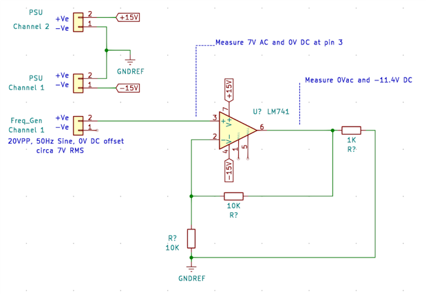
I don't care about quality nor if the signal is clipped - common mode input voltage range is +-13V at 15Vin and I could increase Vin to +-18V.  At the moment, I'm getting a wholly unexpected output which makes me think I'm doing something wrong.  I originally thought it was because I'd got the ground wrong but when I change the ground point of the Op Amp output to the Ground of the Function Generator, it still doesn't work AND channel 1 of the PSU oscillates between 0V and 32V! 


Is there a better way that I can do this with parts that I might have at hand?  Ultimately, I want to be able to variably alter the output voltage level to amounts < 12Vac and alter the frequency (hence why I thought using my frequency generator was a good idea)

  • Sign in to reply
  • Cancel

Top Replies

  • three-phase
    three-phase over 4 years ago +5 verified
    Hello Andrew, Some of my thoughts for you. Do you have the ground from the waveform generator connected to the ground for the op-amp? I would have thought all the grounds should be connected together,…
  • Andrew J
    Andrew J over 4 years ago in reply to shabaz +4
    Donald, Ralph: yes you were both right: 1K was too much of a load and it needed the generator -ve connecting to GNDREF. I'd wrongly assumed that would cause problems given that they belonged to two different…
  • michaelkellett
    michaelkellett over 4 years ago in reply to phoenixcomm +3 suggested
    phoenixcomm You're aiming for 115 * 5 = 575W minimum with a hope for double that. When I needed to do this last I bought a no name mega disco audio amplifier for about £200. It can manage about 1500W out…
Parents
  • three-phase
    0 three-phase over 4 years ago

    Hello Andrew,


    Some of my thoughts for you.


    Do you have the ground from the waveform generator connected to the ground for the op-amp? I would have thought all the grounds should be connected together, they are when I build up an amplifier to increase the output on my waveform generators. From your drawing it looks like the ground for the waveform generator is floating.


    I am not sure of the 1 kOhm resistor from the op-amp output to the ground, is this providing too much load for the op-amp?


    I usually put a resistor in series from the waveform generator into the non-inverting input of the amplifier, to limit current, but I don't think this stops the circuit functioning basically. Same with de-coupling capacitors on the supply rails.


    Have you checked that the PSU and waveform generators have isolated outputs and you aren't creating a circulating current somewhere that is causing your supply to current limit and drop the voltage down to 0V? Not sure why it would then want to go up to 32V though.


    At the moment your amplifier is set up with a 2 to 1 ratio, and putting in a 20Vpp signal. With the supply only being 30Vpp, you would be overdriving the amplifier. What happens if you decrease the input signal down to 10Vpp or even 5Vpp. You would then be within the limits of the power supply rails and output of the op-amp.


    Are you sure the op-amp is good?


    It is the same method as I have used in the past, so it should work for you.


    Kind regards

    • Cancel
    • Vote Up +5 Vote Down
    • Sign in to reply
    • Verify Answer
    • Reject Answer
    • Cancel
Reply
  • three-phase
    0 three-phase over 4 years ago

    Hello Andrew,


    Some of my thoughts for you.


    Do you have the ground from the waveform generator connected to the ground for the op-amp? I would have thought all the grounds should be connected together, they are when I build up an amplifier to increase the output on my waveform generators. From your drawing it looks like the ground for the waveform generator is floating.


    I am not sure of the 1 kOhm resistor from the op-amp output to the ground, is this providing too much load for the op-amp?


    I usually put a resistor in series from the waveform generator into the non-inverting input of the amplifier, to limit current, but I don't think this stops the circuit functioning basically. Same with de-coupling capacitors on the supply rails.


    Have you checked that the PSU and waveform generators have isolated outputs and you aren't creating a circulating current somewhere that is causing your supply to current limit and drop the voltage down to 0V? Not sure why it would then want to go up to 32V though.


    At the moment your amplifier is set up with a 2 to 1 ratio, and putting in a 20Vpp signal. With the supply only being 30Vpp, you would be overdriving the amplifier. What happens if you decrease the input signal down to 10Vpp or even 5Vpp. You would then be within the limits of the power supply rails and output of the op-amp.


    Are you sure the op-amp is good?


    It is the same method as I have used in the past, so it should work for you.


    Kind regards

    • Cancel
    • Vote Up +5 Vote Down
    • Sign in to reply
    • Verify Answer
    • Reject Answer
    • Cancel
Children
  • Andrew J
    0 Andrew J over 4 years ago in reply to three-phase

    Thanks Donald,


    Do you have the ground from the waveform generator connected to the ground for the op-amp? I would have thought all the grounds should be connected together, they are when I build up an amplifier to increase the output on my waveform generators. From your drawing it looks like the ground for the waveform generator is floating.

    No, I have it as you see - not connected.  I didn't think it right to link it's ground to what I have as GNDREF but I can give that a go in the morning if it isn't going to damage anything.  You would connect what I have as Pin1 on the generator to GNDREF?


    Have you checked that the PSU and waveform generators have isolated outputs and you aren't creating a circulating current somewhere that is causing your supply to current limit and drop the voltage down to 0V? Not sure why it would then want to go up to 32V though.

    It only does that if I connect the non-inverting input and output to the ground of the generator rather than GNDREF.


    At the moment your amplifier is set up with a 2 to 1 ratio, and putting in a 20Vpp signal. With the supply only being 30Vpp, you would be overdriving the amplifier. What happens if you decrease the input signal down to 10Vpp or even 5Vpp. You would then be within the limits of the power supply rails and output of the op-amp.

    I don't understand what you mean Donald.  The output of the generator is 20Vpp with a 0V dc offset so +10V/-10V hence the 7Vac  (actually Vac = Vpp/2 * 0.7).  Isn't this within the rail limits of +15V/-15V?  I could set the inputs to +-18V which may prevent top-end clipping but I don't think that's what you are referring to.


    I am not sure of the 1 kOhm resistor from the op-amp output to the ground, is this providing too much load for the op-amp?

    Yes it is!  Removing it will (temporarily) give a x2 output.  But whilst the input stays stable, the output slowly and inexorably drops towards 0V as if the DMM is pulling it down?  At least it's a step forward.


    It is the same method as I have used in the past, so it should work for you.


    That's good to know, at least I'm not a complete idiot image


    It would seem then that the load was wrong but a test circuit in the datasheet includes a 2K resistor on the output.  Any more ideas?

    • Cancel
    • Vote Up +1 Vote Down
    • Sign in to reply
    • Verify Answer
    • Reject Answer
    • Cancel
element14 Community

element14 is the first online community specifically for engineers. Connect with your peers and get expert answers to your questions.

  • Members
  • Learn
  • Technologies
  • Challenges & Projects
  • Products
  • Store
  • About Us
  • Feedback & Support
  • FAQs
  • Terms of Use
  • Privacy Policy
  • Legal and Copyright Notices
  • Sitemap
  • Cookies

An Avnet Company © 2025 Premier Farnell Limited. All Rights Reserved.

Premier Farnell Ltd, registered in England and Wales (no 00876412), registered office: Farnell House, Forge Lane, Leeds LS12 2NE.

ICP 备案号 10220084.

Follow element14

  • X
  • Facebook
  • linkedin
  • YouTube