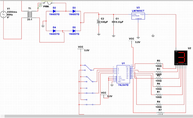
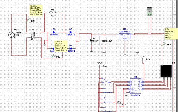
Every time I try to run the circuit the fuse breaks and the display turns off.
also I need the display to be supplied by the five voltage output from the power supply I designed
I attached the multisim file
Be sure to click 'more' and select 'suggest as answer'!
If you're the thread creator, be sure to click 'more' then 'Verify as Answer'!
Every time I try to run the circuit the fuse breaks and the display turns off.
also I need the display to be supplied by the five voltage output from the power supply I designed
I attached the multisim file