element14 Community
element14 Community
    Register Log In
  • Site
  • Search
  • Log In Register
  • Community Hub
    Community Hub
    • What's New on element14
    • Feedback and Support
    • Benefits of Membership
    • Personal Blogs
    • Members Area
    • Achievement Levels
  • Learn
    Learn
    • Ask an Expert
    • eBooks
    • element14 presents
    • Learning Center
    • Tech Spotlight
    • STEM Academy
    • Webinars, Training and Events
    • Learning Groups
  • Technologies
    Technologies
    • 3D Printing
    • FPGA
    • Industrial Automation
    • Internet of Things
    • Power & Energy
    • Sensors
    • Technology Groups
  • Challenges & Projects
    Challenges & Projects
    • Design Challenges
    • element14 presents Projects
    • Project14
    • Arduino Projects
    • Raspberry Pi Projects
    • Project Groups
  • Products
    Products
    • Arduino
    • Avnet Boards Community
    • Dev Tools
    • Manufacturers
    • Multicomp Pro
    • Product Groups
    • Raspberry Pi
    • RoadTests & Reviews
  • Store
    Store
    • Visit Your Store
    • Choose another store...
      • Europe
      •  Austria (German)
      •  Belgium (Dutch, French)
      •  Bulgaria (Bulgarian)
      •  Czech Republic (Czech)
      •  Denmark (Danish)
      •  Estonia (Estonian)
      •  Finland (Finnish)
      •  France (French)
      •  Germany (German)
      •  Hungary (Hungarian)
      •  Ireland
      •  Israel
      •  Italy (Italian)
      •  Latvia (Latvian)
      •  
      •  Lithuania (Lithuanian)
      •  Netherlands (Dutch)
      •  Norway (Norwegian)
      •  Poland (Polish)
      •  Portugal (Portuguese)
      •  Romania (Romanian)
      •  Russia (Russian)
      •  Slovakia (Slovak)
      •  Slovenia (Slovenian)
      •  Spain (Spanish)
      •  Sweden (Swedish)
      •  Switzerland(German, French)
      •  Turkey (Turkish)
      •  United Kingdom
      • Asia Pacific
      •  Australia
      •  China
      •  Hong Kong
      •  India
      •  Korea (Korean)
      •  Malaysia
      •  New Zealand
      •  Philippines
      •  Singapore
      •  Taiwan
      •  Thailand (Thai)
      • Americas
      •  Brazil (Portuguese)
      •  Canada
      •  Mexico (Spanish)
      •  United States
      Can't find the country/region you're looking for? Visit our export site or find a local distributor.
  • Translate
  • Profile
  • Settings
Experts, Learning and Guidance
  • Technologies
  • More
Experts, Learning and Guidance
Ask an Expert Forum Can I use the MCP4241-104E/P with an audio signal?
  • Blog
  • Forum
  • Documents
  • Leaderboard
  • Files
  • Members
  • Mentions
  • Sub-Groups
  • Tags
  • More
  • Cancel
  • New
Join Experts, Learning and Guidance to participate - click to join for free!
Actions
  • Share
  • More
  • Cancel
Forum Thread Details
  • State Suggested Answer
  • Replies 7 replies
  • Answers 2 answers
  • Subscribers 277 subscribers
  • Views 997 views
  • Users 0 members are here
  • pt:digital_potentiometer
  • mechanical_potentiometer_replacement
Related
See a helpful answer?

Be sure to click 'more' and select 'suggest as answer'!

If you're the thread creator, be sure to click 'more' then 'Verify as Answer'!

Can I use the MCP4241-104E/P with an audio signal?

Former Member
Former Member over 12 years ago

Hi,


I'm currently designing a small home made Hi-Fi System and wanted to change the volume potentiometer in the amplifier to a digital potentiometer that I can control with my Raspberry Pi.


It looks like this (MCP4241-104E/PMCP4241-104E/P) 100K Ohm Dual channel linear digital potentiometer might be the one I want, but I'm a bit concerned as to whether it is compatible with the voltages from the average audio Line out.


http://i.imgur.com/T1msf48.png

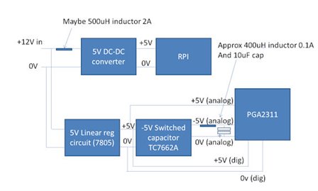
This diagram shows what I currently have on the left, and what I'm planning on doing on the right. The left and right audio lines come straight from the connectors on the back of the amp, so the voltages would be the same as those coming from a PC or an mp3 player etc.. which were less than 1V when I mesasured it with my multimeter.


I've checked the Datasheet and it seems like this should be ok, but I wanted to ask an expert just in-case I've missed something and / or not completely understood the specifications!


Further info:

  • I'm planning on providing VDD with 3.3V from the raspberry Pi as that is the voltage for the GPIO pins I belive.
  • The original mechanical potentiometer is a 100K Ohm Linear pot, so this should match up pretty well. (Photo here)
  • A photo of the underside of the Amp to show that the volume pot comes straight out of the input connectors: http://i.imgur.com/bwCRa7gh.jpg
  • A photo of the top of the Amp showing the OpAmp that the pot feeds into: http://i.imgur.com/DQ1ReWIh.jpg


I appreciate any help you can give me, so thank you in advance!


- James

  • Sign in to reply
  • Cancel
  • shabaz
    0 shabaz over 12 years ago

    Hi James,


    The line input level can vary a lot from device to device, even though there is supposed to be a reference level (I forget what it is). For example, the iPod line out on it's

    dock connector (old connector) is lower (maybe 0.5-1Vp-p from memory). That ic that you reference can support inputs up to the supply voltage,

    and this will be sufficient for line input voltage levels.


    Although it should work, if you want better sound, it could be worth replacing the device, since the MCP.. is not specially designed for audio applications (you can tell this because of little

    information in the datasheet related to AC characteristics). Something like PGA2311 would work, but it is expensive (with audio, you really will hear even the slightest noise since the ear

    has such a high dynamic range, so worth buying a nice ic for this if appropriate for your design).

    The PGA2311 requires a separate analog supply, so admittedly it's not as convenient. It uses 5V logic levels, but this should still be compatible with the RPI since you will be

    only using the SCLK and SDI pins, and not SDO.

    There are other ics too, but they all seemed as expensive or more.

    • Cancel
    • Vote Up 0 Vote Down
    • Sign in to reply
    • Verify Answer
    • Reject Answer
    • Cancel
  • Former Member
    0 Former Member over 12 years ago in reply to shabaz

    Thanks Shabaz that's really helpful!


    The PGA2311 seems like the perfect choice for what I'm doing so I'll definitely go with that I think.


    In terms of the analog power supply would something like this be appropriate? (http://www.electronicsteacher.com/circuits-and-diagrams/power-supplies-and-control-schematics/ckt21_1.gif). This is my first time delving into -5V which isn't that scary, but I just want to make sure I'm going in the right direction!

    • Cancel
    • Vote Up 0 Vote Down
    • Sign in to reply
    • Verify Answer
    • Cancel
  • shabaz
    0 shabaz over 12 years ago in reply to Former Member

    Hi James,


    The supply circuit you mention will be good, it is a linear supply and low noise. If you wish to power the entire circuit from a single supply (assuming you have a 5V supply available which will also power the RPi),

    then another way is to use something like TC7662A, which can convert a +5V supply into a -5V supply (figure 4-1 in the datasheet). It is a switched capacitor design, which needs 2 capacitors to function.

    You may get some power supply noise into your audio with this however (although it will be at 12kHz and higher, so you're possibly unlikely to hear it). More likely, you may get noise from the RPi or from the +5V supply, and it will be difficult to get rid of it all (since ears are extremely sensitive). There are some things you could do to minimize noise, but it's hard to be sure what will be effective. To start, keep your audio part as far away from the RPi as possible. There are PCB layout guidelines for the PGA.., so these could be followed too.

    • Cancel
    • Vote Up 0 Vote Down
    • Sign in to reply
    • Verify Answer
    • Reject Answer
    • Cancel
  • Former Member
    0 Former Member over 12 years ago in reply to shabaz

    Ahh that looks more convenient, thanks! I just found a 5V switching regulator in my parts draw (http://www.dimensionengineering.com/datasheets/DE-SW0XX.pdf), so I was thinking that I could use that to regulate a 12V transformer down to 5V which could the power both the RPi, and the TC7662A in one go. If I placed the regulator and the TC7662A + Caps on a separate PCB and then also made sure that the digital lines were on a completely different ground plane to the analog lines (Although a single connection between them as per the datasheet's instructions), would that be ok noise wise?

    • Cancel
    • Vote Up 0 Vote Down
    • Sign in to reply
    • Verify Answer
    • Cancel
  • shabaz
    0 shabaz over 12 years ago in reply to Former Member

    That looks absolutely ideal for powering the RPI, but these small ready-built switchers sometimes have quite high ripple and noise, so maybe some strategy like this could be worth considering

    (excuse the poor diag). Some of this is just trial-and-error, it may not be the best approach.

    Here, +5V analog supply is via the low-cost 7805 linear supply circuit, it doesn't need a heatsink, it could possibly be a smaller 78L05 depending on power dissipation calculations (I didn't do the calc)

    or could be a LP2950-5 for example. The -5V analog supply is using the TCA7662A followed by an optional LC filter. The values are not critical, just ballpark (to provide filter freq below 12kHz). Note the capacitor +ve end goes to 0v (hard to see on the crude diag).

    image

    • Cancel
    • Vote Up 0 Vote Down
    • Sign in to reply
    • Verify Answer
    • Cancel
  • Former Member
    0 Former Member over 12 years ago in reply to shabaz

    Ahh great, I've reproduced your schematic in eagle, but I wasn't too sure about the inductors:


    • 500µH 2A: http://uk.farnell.com/bourns-jw-miller/5256-rc/choke-500uh-2a-20-990khz/dp/1103553
    • 400µH 0.1A: I couldn't find any at this spec 400µH inductors were all roughly 3.6A..

    Also, would the 0V analog need to be completely separate to the 0V in the rest of the circuit? I was thinking of just having 3 Screw terminals with +5V 0V and -5V that could then be routed to the audio PCB with the PGA2311.
    image

    Sorry if it's a bit messy! And thanks for your help, I really appreciate it!


    Edit: I forgot to add some capacitors into the 7805 circuit, probably a 100µF capactitor on the 12V side and a 100nF capcacitor on the 5V side.

    • Cancel
    • Vote Up 0 Vote Down
    • Sign in to reply
    • Verify Answer
    • Cancel
  • shabaz
    0 shabaz over 12 years ago in reply to Former Member

    Hello,


    Thinking about this more last night, I had some suggestions. Firstly, the inductors:

    For something close to 400uH 0.1A, you could use this one. This is 470uH so a bit higher than needed, but this is fine.

    For the 500uH 2A, I just noticed the switcher datasheet says it run at a much higher freq, so you can use a far lower

    value, 10uH would be ok. This one should be fine (it is 1.6A).

    Regarding the rest of the topology, there is another improvement but it involves an additional regulator, the 79L05

    which is small (TO92 sized). Basically, you could power the TC7662A from 12V instead of 5V, and then it will generate -12V.

    Then, you could use the 79L05 to regulate to -5V. It may be overkill, but just something to consider.

    Regarding routing of wires, you are probably ok with your suggestion. The usual approach is to have separate wires from the

    supply (7805/TC7662A in this case), so that the path for current to flow from the digital supply rail through the PGA and

    into the 0V rail is kept separate from the analog path. So in other words, with the diagram above, two wires or paths from close to

    the OUT pin of the 7805 to your PGA, and two wires or paths close from the 0v area near the 7805 and TC7662A to the PGA.

    As you say, the 100nF on 5V side of 7805 would be needed. Even 10uF or lower on input side to 7805 would be ok.

    • Cancel
    • Vote Up 0 Vote Down
    • Sign in to reply
    • Verify Answer
    • Cancel
element14 Community

element14 is the first online community specifically for engineers. Connect with your peers and get expert answers to your questions.

  • Members
  • Learn
  • Technologies
  • Challenges & Projects
  • Products
  • Store
  • About Us
  • Feedback & Support
  • FAQs
  • Terms of Use
  • Privacy Policy
  • Legal and Copyright Notices
  • Sitemap
  • Cookies

An Avnet Company © 2025 Premier Farnell Limited. All Rights Reserved.

Premier Farnell Ltd, registered in England and Wales (no 00876412), registered office: Farnell House, Forge Lane, Leeds LS12 2NE.

ICP 备案号 10220084.

Follow element14

  • X
  • Facebook
  • linkedin
  • YouTube