element14 Community
element14 Community
    Register Log In
  • Site
  • Search
  • Log In Register
  • Community Hub
    Community Hub
    • What's New on element14
    • Feedback and Support
    • Benefits of Membership
    • Personal Blogs
    • Members Area
    • Achievement Levels
  • Learn
    Learn
    • Ask an Expert
    • eBooks
    • element14 presents
    • Learning Center
    • Tech Spotlight
    • STEM Academy
    • Webinars, Training and Events
    • Learning Groups
  • Technologies
    Technologies
    • 3D Printing
    • FPGA
    • Industrial Automation
    • Internet of Things
    • Power & Energy
    • Sensors
    • Technology Groups
  • Challenges & Projects
    Challenges & Projects
    • Design Challenges
    • element14 presents Projects
    • Project14
    • Arduino Projects
    • Raspberry Pi Projects
    • Project Groups
  • Products
    Products
    • Arduino
    • Avnet & Tria Boards Community
    • Dev Tools
    • Manufacturers
    • Multicomp Pro
    • Product Groups
    • Raspberry Pi
    • RoadTests & Reviews
  • About Us
  • Store
    Store
    • Visit Your Store
    • Choose another store...
      • Europe
      •  Austria (German)
      •  Belgium (Dutch, French)
      •  Bulgaria (Bulgarian)
      •  Czech Republic (Czech)
      •  Denmark (Danish)
      •  Estonia (Estonian)
      •  Finland (Finnish)
      •  France (French)
      •  Germany (German)
      •  Hungary (Hungarian)
      •  Ireland
      •  Israel
      •  Italy (Italian)
      •  Latvia (Latvian)
      •  
      •  Lithuania (Lithuanian)
      •  Netherlands (Dutch)
      •  Norway (Norwegian)
      •  Poland (Polish)
      •  Portugal (Portuguese)
      •  Romania (Romanian)
      •  Russia (Russian)
      •  Slovakia (Slovak)
      •  Slovenia (Slovenian)
      •  Spain (Spanish)
      •  Sweden (Swedish)
      •  Switzerland(German, French)
      •  Turkey (Turkish)
      •  United Kingdom
      • Asia Pacific
      •  Australia
      •  China
      •  Hong Kong
      •  India
      • Japan
      •  Korea (Korean)
      •  Malaysia
      •  New Zealand
      •  Philippines
      •  Singapore
      •  Taiwan
      •  Thailand (Thai)
      • Vietnam
      • Americas
      •  Brazil (Portuguese)
      •  Canada
      •  Mexico (Spanish)
      •  United States
      Can't find the country/region you're looking for? Visit our export site or find a local distributor.
  • Translate
  • Profile
  • Settings
Experts, Learning and Guidance
  • Technologies
  • More
Experts, Learning and Guidance
Ask an Expert Forum Which surface mount resistor is this?
  • Blog
  • Forum
  • Documents
  • Leaderboard
  • Files
  • Members
  • Mentions
  • Sub-Groups
  • Tags
  • More
  • Cancel
  • New
Join Experts, Learning and Guidance to participate - click to join for free!
Actions
  • Share
  • More
  • Cancel
Forum Thread Details
  • State Verified Answer
  • Replies 19 replies
  • Answers 2 answers
  • Subscribers 306 subscribers
  • Views 2464 views
  • Users 0 members are here
  • smr
Related
See a helpful answer?

Be sure to click 'more' and select 'suggest as answer'!

If you're the thread creator, be sure to click 'more' then 'Verify as Answer'!

Which surface mount resistor is this?

hafcanadian
hafcanadian over 10 years ago

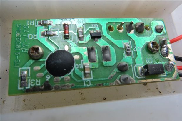
I can't find a local source for a SMR that somehow got knocked off an outdoor solar lantern's PCB while I was trying to refurbish it.  Thankfully I had another device and could look to see which one it was.  But I can't figure out what to order online.  I took both devices to a well-known local electronics store, but the tech at the counter looked at the intact one with a magnifying glass but couldn't tell me which SMR I needed either. 
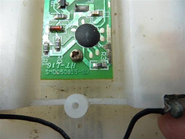
The numbers on it are either 1101 or 1011.  I can't tell which direction to read it, and am no electronics expert by any means.  Attached are photos of the intact and functional PCB.  The SMR I need another of is in position R3.  Can anyone advise me which one of many offered by Element 14's catalog is correct?


Thanks,

Joel

imageimage

  • Sign in to reply
  • Cancel

Top Replies

  • mcb1
    mcb1 over 10 years ago in reply to hafcanadian +2
    I take it that it doesn't matter in this application what the resistor's specifications are, such as milliwatts, voltage, case style? In this application probably not... EXCEPT the case style needs…
  • Robert Peter Oakes
    Robert Peter Oakes over 10 years ago +1 verified
    It is either a 1.1k or a 1.01k and I would think either would work in your circuit Regards
  • mcb1
    mcb1 over 10 years ago in reply to Robert Peter Oakes +1 suggested
    You should also be able to measure it. If you really wanted, a small cut on the track below or right of the silkscreen R3 would isolate it. The cut is easy to fix with some solder. Mark
  • Robert Peter Oakes
    0 Robert Peter Oakes over 10 years ago

    It is either a 1.1k or a 1.01k and I would think either would work in your circuit


    Regards

    • Cancel
    • Vote Up +1 Vote Down
    • Sign in to reply
    • Reject Answer
    • Cancel
  • mcb1
    0 mcb1 over 10 years ago in reply to Robert Peter Oakes

    You should also be able to measure it.


    If you really wanted, a small cut on the track below or right of the silkscreen R3 would isolate it.

    The cut is easy to fix with some solder.


    Mark

    • Cancel
    • Vote Up +1 Vote Down
    • Sign in to reply
    • Verify Answer
    • Reject Answer
    • Cancel
  • gadget.iom
    0 gadget.iom over 10 years ago

    I would agree with Robert Peter Oakes on this one...


    These unsoldered terminals make me shudder:

    image

    • Cancel
    • Vote Up 0 Vote Down
    • Sign in to reply
    • Verify Answer
    • Reject Answer
    • Cancel
  • hafcanadian
    0 hafcanadian over 10 years ago in reply to gadget.iom

    Thanks Peter and Paul.  Those aren't unsoldered terminals;  the two at each end are guide pins at either end of a slide switch housing on the other side of the board.  Two in the middle are contact pins for "ON" and the third unsoldered one is for the "OFF" position contact.


    The only shuddering necessary is if you were to see my earlier greenhorn soldering attempts on the other PCB that has the missing surface mount resistor.  When I get a new SMR for it, I'll try to use my new Hakko iron, 65/35 solder, flux pen and flux remover pen, and hopefully better technique to clean that mess up.  With age has come a tremor that makes fine-circuit soldering particularly difficult, even with "helping hands"/magnifier, so results aren't always as pretty as I'd like.


    I guess I'll go for one of the "1101" resistors in Newark's catalog.  I take it that it doesn't matter in this application what the resistor's specifications are, such as milliwatts, voltage, case style?   http://www.newark.com/webapp/wcs/stores/servlet/Search?catalogId=15003&langId=-1&storeId=10194&gs=true&st=surface%20mount%20resistor%201101


    Joel

    • Cancel
    • Vote Up +1 Vote Down
    • Sign in to reply
    • Verify Answer
    • Cancel
  • gadget.iom
    0 gadget.iom over 10 years ago in reply to hafcanadian

    I personally prefer all contacts to be soldered on a switch. If only to increase the mechanical durability.

    • Cancel
    • Vote Up 0 Vote Down
    • Sign in to reply
    • Verify Answer
    • Cancel
  • mcb1
    0 mcb1 over 10 years ago in reply to hafcanadian

    I take it that it doesn't matter in this application what the resistor's specifications are, such as milliwatts, voltage, case style?

    In this application probably not... EXCEPT the case style needs to match the spacing of the pads.

    Try this link to work out which one

    http://www.resistorguide.com/resistor-sizes-and-packages/


    Shaky hands and small work are an issue (without adding age).

    When we teach pupils to solder, I often suggest resting the edge of the hand opposite your thumb on the workbench, just to steady it.


    You might find that Bluetac to hold the board in place on a flat surface, and a suitable bent wire to hold the smd resistor in the right place will help you, while adding some solder to each end.


    Mark

    • Cancel
    • Vote Up +2 Vote Down
    • Sign in to reply
    • Verify Answer
    • Cancel
  • hafcanadian
    0 hafcanadian over 10 years ago in reply to mcb1

    Say, that was quite helpful, Mark.  Thanks.  I could finally interpret the numbers on the SMD, although it would still be good to know which direction to read them;  the "1's" don't have tails on their font style, so I can't tell which way is up.  Weird, since some of the other SMD's on the board use a more intelligible font, with tails on their "1's".  Regardless, it deciphers to either an 1100 or a 1010 ohm resistor.  Hopefully the 90 ohm difference isn't significant in this application.  The calculator on one page of the resistorguide link you provided was a cool tool, although by then I'd already calculated the resistance values myself from the text and confirmed them via the video they provided.


    I did try to measure the SMD in question with my digital calipers, but the solder on the ends and the fact it was tight to the board compromised any precision.  I got 2.0mm long X 1.36mm wide X 0.6mm high.  I should be able to go to Newark's catalog and ferret out a plausible candidate.


    The Bluetac may be a better solution than the "helping hands" magnifier, since I could brace both hands on the worksurface.  Ben Heck demonstrates the use of tweezers for these small devices, on his Element14 program online, so I got a pair of ESD safe ones.  One place my tremor gives me fits is presoldering small gauge multistranded wire ends.  Ben makes it look easy, but he obviously has no shaking goin' on.  But the Hakko iron and better cleaning and tinning habits certainly have made life easier than when I struggled with my old Weller or Dremel handpieces, using fine sandpaper to clean its tip (gag), and could never get solder to melt when wire was between the solder and the iron.  The Hakko is a dream.


    Joel

    • Cancel
    • Vote Up 0 Vote Down
    • Sign in to reply
    • Verify Answer
    • Cancel
  • mcb1
    0 mcb1 over 10 years ago in reply to hafcanadian

    hafcanadian

    Glad it was useful.


    I think you'll see form the ilnk you only need to be close to work out which of the packages it is, so the width should be enough.

    From your measurements it is an 0805 package.


    I did suggest cutting the track to measure it with an ohmmeter, but I don't think 90 ohms will make a difference as I suspect it is simply a pulldown for the pin.


    I struggled with my old Weller handpiece, using fine sandpaper to clean its tip (gag)

    Removing the plating is not the best way to encourage the solder to stick.


    I would use the steel wool type tip cleaners, that are available from here, or in your local supermarket.

    There was a discussion here.

    http://www.newark.com/weller/t0051384199/brass-wool-replacement-wdc-2-pk2/dp/71R4748?ost=1792732


    Mark

    • Cancel
    • Vote Up 0 Vote Down
    • Sign in to reply
    • Verify Answer
    • Cancel
  • Problemchild
    0 Problemchild over 10 years ago in reply to mcb1

    Even better of course would be the dedicated tip cleaning products like those brass tailings in a tray with some flux on them.

    Much better than the old damp sponge and very mildly abrasive to clear off the oxidized clag.


    http://cpc.farnell.com/pro-s-kit/sh-1025/cleaner-soldering-tip/dp/SD01015?ost=tip+cleaner&categoryId=700000008630


    image

    • Cancel
    • Vote Up +1 Vote Down
    • Sign in to reply
    • Verify Answer
    • Cancel
  • hafcanadian
    0 hafcanadian over 10 years ago in reply to Problemchild

    Yes, thanks Guys.  The Hakko (model FX888-23BY) came with an iron rest that includes a really nice sponge and a brass wool pocket.  I've found I don't really use sponges anymore, although in my earliest years I didn't use them at all (didn't know any better).  The brass wool alone and cleaning by tinning with flux core solder has been keeping my new iron tips beautiful, so I don't bother wetting the sponge. 


    Someone told me one reason for my noticed improvement is that the Hakko uses ceramic tip cores, so the heat is better controlled than on my simple Weller and Dremel wands.  I "learned" initially with Dad's old 1950's Weller 2-level triggered gun, but it was heavy and the heat hard to control;  not much good for today's fine electronic PCB's.  They still sell a similar one today, but it's not as well built - overseas quality shall we say.  So I keep Dad's around for heavy automotive soldering, etc.


    I ordered a Vishay Dale thick film resistor, 1.1 ohm, 125mW, 150v, at 1% tolerance earlier this afternoon, so you've confirmed my dimensional analysis at 0805 (Newark part 52K9729).  Seemed silly... the SMD was 8 cents, the shipping $6;  but I needed no other components at the moment.  Go figure, they can't put that dinky thing in an envelope and mail it for 49 cents.


    Joel

    • Cancel
    • Vote Up 0 Vote Down
    • Sign in to reply
    • Verify Answer
    • Cancel
>
element14 Community

element14 is the first online community specifically for engineers. Connect with your peers and get expert answers to your questions.

  • Members
  • Learn
  • Technologies
  • Challenges & Projects
  • Products
  • Store
  • About Us
  • Feedback & Support
  • FAQs
  • Terms of Use
  • Privacy Policy
  • Legal and Copyright Notices
  • Sitemap
  • Cookies

An Avnet Company © 2025 Premier Farnell Limited. All Rights Reserved.

Premier Farnell Ltd, registered in England and Wales (no 00876412), registered office: Farnell House, Forge Lane, Leeds LS12 2NE.

ICP 备案号 10220084.

Follow element14

  • X
  • Facebook
  • linkedin
  • YouTube