element14 Community
element14 Community
    Register Log In
  • Site
  • Search
  • Log In Register
  • About Us
  • Community Hub
    Community Hub
    • What's New on element14
    • Feedback and Support
    • Benefits of Membership
    • Personal Blogs
    • Members Area
    • Achievement Levels
  • Learn
    Learn
    • Ask an Expert
    • eBooks
    • element14 presents
    • Learning Center
    • Tech Spotlight
    • STEM Academy
    • Webinars, Training and Events
    • Learning Groups
  • Technologies
    Technologies
    • 3D Printing
    • FPGA
    • Industrial Automation
    • Internet of Things
    • Power & Energy
    • Sensors
    • Technology Groups
  • Challenges & Projects
    Challenges & Projects
    • Design Challenges
    • element14 presents Projects
    • Project14
    • Arduino Projects
    • Raspberry Pi Projects
    • Project Groups
  • Products
    Products
    • Arduino
    • Avnet Boards Community
    • Dev Tools
    • Manufacturers
    • Multicomp Pro
    • Product Groups
    • Raspberry Pi
    • RoadTests & Reviews
  • Store
    Store
    • Visit Your Store
    • Choose another store...
      • Europe
      •  Austria (German)
      •  Belgium (Dutch, French)
      •  Bulgaria (Bulgarian)
      •  Czech Republic (Czech)
      •  Denmark (Danish)
      •  Estonia (Estonian)
      •  Finland (Finnish)
      •  France (French)
      •  Germany (German)
      •  Hungary (Hungarian)
      •  Ireland
      •  Israel
      •  Italy (Italian)
      •  Latvia (Latvian)
      •  
      •  Lithuania (Lithuanian)
      •  Netherlands (Dutch)
      •  Norway (Norwegian)
      •  Poland (Polish)
      •  Portugal (Portuguese)
      •  Romania (Romanian)
      •  Russia (Russian)
      •  Slovakia (Slovak)
      •  Slovenia (Slovenian)
      •  Spain (Spanish)
      •  Sweden (Swedish)
      •  Switzerland(German, French)
      •  Turkey (Turkish)
      •  United Kingdom
      • Asia Pacific
      •  Australia
      •  China
      •  Hong Kong
      •  India
      •  Korea (Korean)
      •  Malaysia
      •  New Zealand
      •  Philippines
      •  Singapore
      •  Taiwan
      •  Thailand (Thai)
      • Americas
      •  Brazil (Portuguese)
      •  Canada
      •  Mexico (Spanish)
      •  United States
      Can't find the country/region you're looking for? Visit our export site or find a local distributor.
  • Translate
  • Profile
  • Settings
Experts, Learning and Guidance
  • Technologies
  • More
Experts, Learning and Guidance
Ask an Expert Forum For FET-sake, I keep switching and cannot find a suitable MOSFET (or BJT)
  • Blog
  • Forum
  • Documents
  • Leaderboard
  • Files
  • Members
  • Mentions
  • Sub-Groups
  • Tags
  • More
  • Cancel
  • New
Join Experts, Learning and Guidance to participate - click to join for free!
Actions
  • Share
  • More
  • Cancel
Forum Thread Details
  • State Suggested Answer
  • Replies 33 replies
  • Answers 12 answers
  • Subscribers 286 subscribers
  • Views 7043 views
  • Users 0 members are here
  • mosfet relay
  • transistor switch
Related
See a helpful answer?

Be sure to click 'more' and select 'suggest as answer'!

If you're the thread creator, be sure to click 'more' then 'Verify as Answer'!

For FET-sake, I keep switching and cannot find a suitable MOSFET (or BJT)

BigG
BigG over 3 years ago

I came across this lovely term on Twitter the other day for tablet and laptop battery packs that had seen better days (usually when continuously powered/charged). It's #spicy pillow. LOL.


https://twitter.com/hashtag/spicypillow?lang=en


Anyway, this reminded me of a little project I had in mind (as shown in schema below).


image

As a electronics novice, this appears to be a borderline case as I know that transistors tend to work well for mA switches while MOSFETs tend to be targeted at higher voltages (and say +3A current).


So now struggling to choose a suitable component - I'm particularly interested at the 1.5A option as that tends to be the limit for many usb charger adapters:


image


Having done some prelim research it looks like FET's are the way to go but when working through my design criteria I'm quickly getting bogged down in the detail... In this case I'm not coming up with options as I can see that I need to minimise my resistance losses to reduce voltage drop etc... I'm also looking for a low cost <1$ SMD option.


Hence I thought to open this little design challenge to the members as I had to chuckle at aGough Lui status update I found when doing my e14 search...


Often we're lazy, choosing to use the same parts over and over. I'm guilty of this when it comes to...


So, any old favourite FETs you have which could well work here?

  • Sign in to reply
  • Cancel

Top Replies

  • michaelkellett
    michaelkellett over 3 years ago +7 suggested
    Don't have favourites. Always use a part for a reason (usually many reasons). Having a reel of 999 of a part is a good reason if it will work OK ! In your case with 3.3V drive, 5V power supply, a load…
  • colporteur
    colporteur over 3 years ago +3 suggested
    Absolutely loved the title of your post! You have to start writing for British tabloids. I missed the meaning of the hashtag. I have little exposure to the sun or social media from under the bridge I only…
  • BigG
    BigG over 3 years ago in reply to colporteur +3 suggested
    LOL. (British tabloids) I missed the meaning of the hashtag. Batteries look like pillows. As to where "spicy" came from, who knows, so I had to look it up (thanks Google) https://www.urbandictionary.com…
  • BigG
    0 BigG over 3 years ago in reply to shabaz

    Thanks for the feedback. That's a very interesting option. I have no idea if my laptop offers such an option. I'll have to check this out.

    Searching online, I see there's a few blogs about lithium-ion charging cycles. Some mention temperature as being one of the contributing factors.

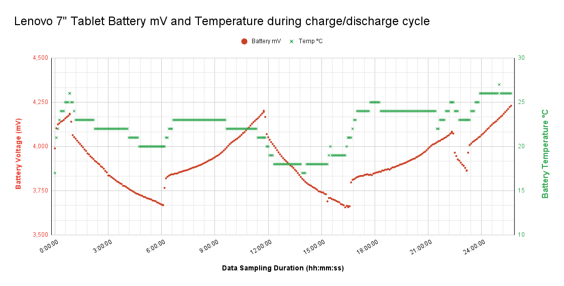
    As the battery widget within the app code captured temperature, I thought to log that data too. Here's the results. I noticed that the minimum temperatures were overnight when the tablet was discharging and there was no central heating on.

    I'm thinking that I could readily include temperature as one of the parameters too, to determine when to stop or pause charging the battery... it seems like 24 degrees is the plateau and then it peaks above 25 degrees on occasion, although not sure why based on this data as not always consistent (temp data between 10h and 12h seems off - maybe it was because the tablet was idle).

    image

    • Cancel
    • Vote Up +1 Vote Down
    • Sign in to reply
    • Verify Answer
    • Cancel
  • shabaz
    0 shabaz over 3 years ago in reply to BigG

    That's really great! Awesome seeing it work like that on the chart. I'm tempted to make this one day : ) I think it could make our mobile phones last longer. Bit ridiculous that I'm at home mostly and yet charging my phone to 100% every night, and within a year the battery life has noticeably dropped.

    Regarding algorithm, I don't know whats best, but my laptop has a 50% mode, which I've set it to, and it permanently maintains that, I.e. it doesn't drop below about 48% ever I guess.. So I'm presuming that is supposed to keep the life extended, while at the same time providing a reasonable level in case I did need to disconnect from the supply for a few hours. I use that 50% mode (there is no other option other than normal 100% charge) since the laptop is connected to the power brick 99% of the time, since it gets used more like a desktop. 

    • Cancel
    • Vote Up +1 Vote Down
    • Sign in to reply
    • Verify Answer
    • Cancel
  • BigG
    0 BigG over 3 years ago in reply to shabaz

    Yes I've made the very big assumption that current leakage will be contained. Yep, I'm overly optimistic.

    Thankfully, at the moment it seems to be working fine with my normal USB charger.

    I've been doing some tests.

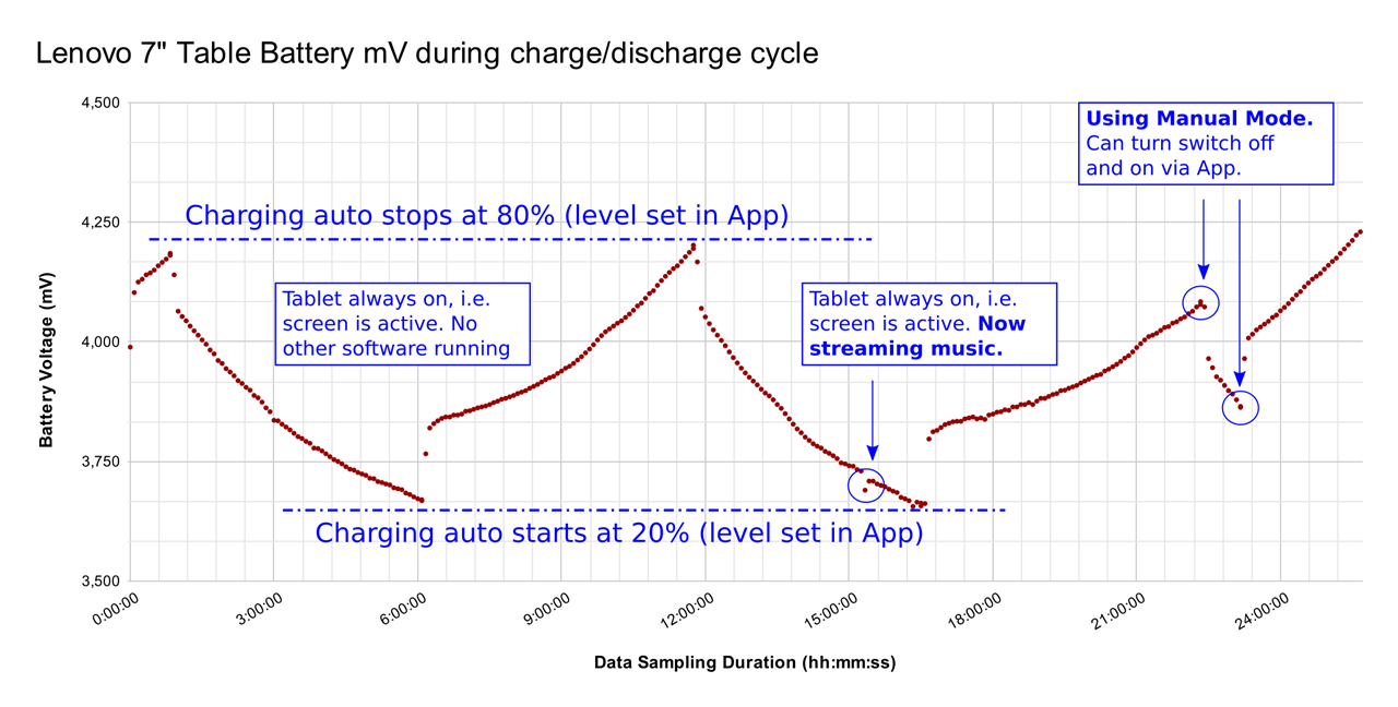
    I've updated my basic BLE switching firmware and have developed a battery monitoring test app for my Android tablet, which has provided some nice data so far. The test app pushes data straight to Google Sheets, which is extra handy. It's doing what I intended, so quite pleased.

    Here's the battery voltage results so far (the battery voltage come via Android OS):

    image

    I can now play around within the app and create my own charging discharging logic. I am now wondering how long I should keep the charger active for, when fully charged or is this the way to do it, as in, hit your max limit then switch off charging until nearly discharged then kick in again.

    • Cancel
    • Vote Up +1 Vote Down
    • Sign in to reply
    • Verify Answer
    • Cancel
  • shabaz
    0 shabaz over 3 years ago in reply to BigG

    Hi Colin,

    Good document. I normally use the circuit #4 they refer to, but the single-chip would definitely be a more compact option. With the circuit #4, you wouldn't need the capacitor they have there, so that reduces the size a bit. Both options are good and could solve any unexpected current paths.

    • Cancel
    • Vote Up +1 Vote Down
    • Sign in to reply
    • Verify Answer
    • Cancel
  • BigG
    0 BigG over 3 years ago in reply to shabaz

    Hi Shabaz,

    While I'm waiting for my next prototype PCB design to be fabricated and delivered I've been exploring alternatives, and I just discovered this application note from TI on load switch IC's.

    Very interesting and it certainly offers a solution for 5V/500mA as per your suggestion.

    https://www.ti.com/lit/an/slva716a/slva716a.pdf

    BR

    Colin

    • Cancel
    • Vote Up +1 Vote Down
    • Sign in to reply
    • Verify Answer
    • Cancel
  • BigG
    0 BigG over 3 years ago in reply to shabaz

    Thanks Shabaz. It's getting there. More often than not you learn more through failures. As such your earlier replies about the D+ D- termination resistors and Battery Charging Negotiation Capability are finally beginning to make better sense. And hence sticking with this approach until I've run out of ideas.

    Your comments in your Silicon Labs roadtest review are proving very insightful. For example:

    "The USB power delivery is often negotiated, because it cannot be assumed that the power source has sufficient capability to power the load. "

    Standard Downstream Port – "If the USB device goes into USB Suspend then technically only 2.5mA is available."

    Apple and Samsung (and other vendor) proprietary schemes – "Depending on the DC voltage on the two pins, the remote device knows how much current it can draw."

    Dedicated Charging Port –"There is a fixed resistance between the two data pins. If the remote device detects this, then it will draw up to 1.5A."

    Charging Downstream Port – "By examining the voltage levels it will determine if the far end is operating in this CDP mode and the device will know it can draw up to 1.5A."

    What is still unknown is the applied tolerance to these various charging rules. The Cypress diagram explaining Rp, Rd, and Ra termination resistors has 5% and 20% tolerances for kOhm resistors. So that gives wriggle room.

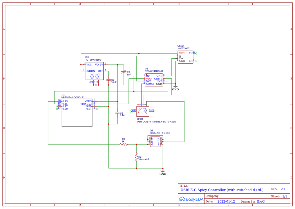
    As such I'm thinking that I can use an Analog Switch IC to disable the Data Lines altogether, which will then tell the smart charger that the phone has been removed (this is what I want) and then when I set the switch to Normally Closed it will introduce less than 10ohms of added resistance, which is hopefully well within the tolerances and thus won't change the charging algorithms.

    I've already gone and modified my schematic and pcb design. This uses a TS3A4741DCNR dual channel SPST analog switch from Texas Instruments. Hopefully this is a good choice. At least it will be easier to solder than that Si1442DH FET I'm using. That was the smallest component I've hand soldered to date.

    image

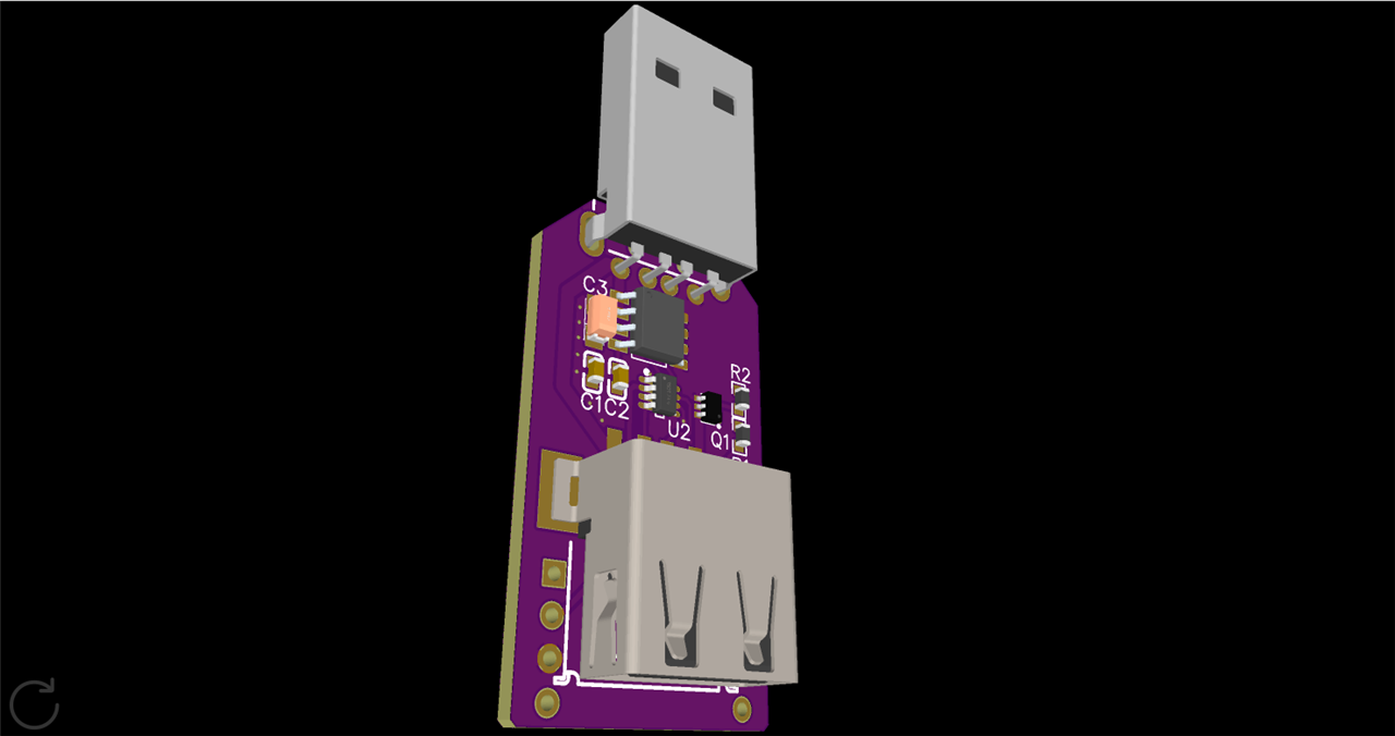
    The 3d render looks pretty cool too.

    image

    • Cancel
    • Vote Up +1 Vote Down
    • Sign in to reply
    • Verify Answer
    • Cancel
  • shabaz
    0 shabaz over 3 years ago in reply to BigG

    Hi Colin, 

    Great project! It may be worth getting a USB plug and socket separately and wire them up 1:1 (or buy a USB extension cable and split it to access the wires) and see what happens if one or both data lines are cut. Also, it may be worth considering cutting the +5V rather than the 0V connection, to see if that makes a difference. There may be a risk of powering up circuitry if the 5V is not cut, because the end device (phone or whatever) could be powering things at low current, through 5V and one of the data lines, since it's an unknown (to me anyway) how the smart charger negotiates the higher voltage. Also for this project, maybe the smart charger is not needed, since if the aim is to run a device for extended periods then you'd only want to charge to say 50% anyway, and keep it there, which is feasible with 500mA.

    • Cancel
    • Vote Up 0 Vote Down
    • Sign in to reply
    • Verify Answer
    • Cancel
  • BigG
    0 BigG over 3 years ago

    As you know, from this forum post I started developing a USB BLE power or "spicy" controller a couple of months ago and thanks to your help I got a prototype (version 1) working.

    I've now been working on a version 2.

    The purpose behind this version is to get a controller to interface both with these new USB smart fast chargers, which work at higher voltage and a higher charging current, as well as a standard 5V USB charger -  my fast USB charger for my Samsung Galaxy A12 charges at approx. 9V and +1.5A.

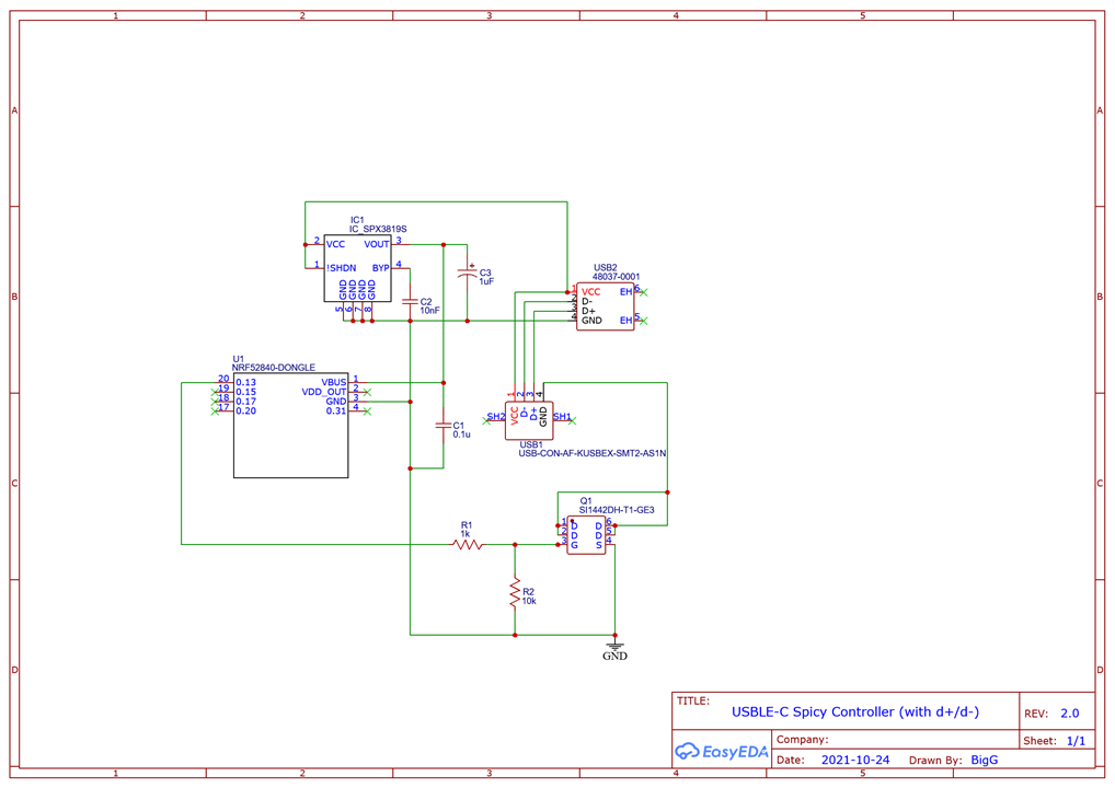
    My design for this new version is as follows:

    image

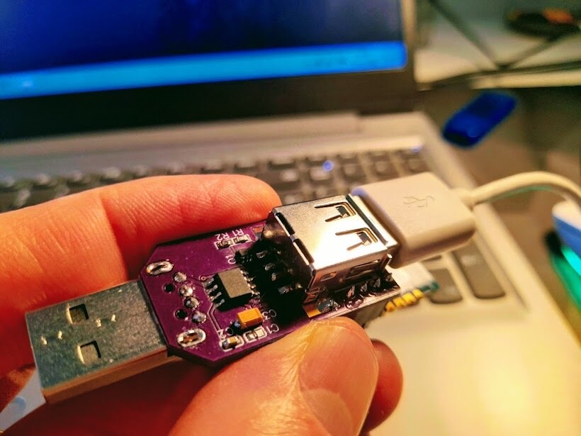
    It now includes a 500mA LDO (SPX3819 from MaxLinear) to drop the voltage to 5V for the BLE dongle and also uses a different N-Channel MOSFET (I'm using Si1442DH from Vishay which provides Vds @ 12V, Vgs @ 8V, Id @ 4A).

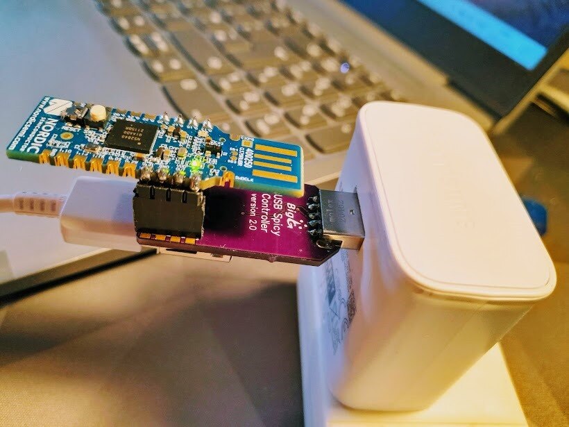
    {gallery}Spicy Controller V2

    image

    image

    I'm pleased to say that it works very well with the standard USB 5V charger...and here is the moment of truth video (my very first test using the new version)

    You don't have permission to edit metadata of this video.
    Edit media
    x
    image
    Upload Preview
    image

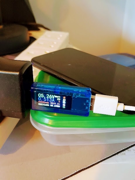
    So there was some power loss (image below show power result without using the controller device). Nevertheless, I'm pretty pleased considering that this is pre design optimization.

    image

    But it is not working properly with the smart fast charger.

    Yep, I discovered another problem for which I need further advice on.

    You don't have permission to edit metadata of this video.
    Edit media
    x
    image
    Upload Preview
    image

    Hopefully the video made sense.

    So, when the USB voltage line for the phone is disabled via the MOSFET switch the USB smart charger switches off power when I plug the phone in but it works fine when throughput voltage enabled.

    So I'm assuming that the issue lies with the data lines and thus I thinking I need some way to disable these when power is off and enable when power is on.

    I'm thinking that an NC or NO 1 or 2 channel analog switch IC would work here. If so is it necessary to switch both data lines (hence using a 2 channel switch) or could I get away with controlling just one of the data lines, like D+ for example, with a 1 channel switch.

    If this is not the right component to use what else might work here.

    As always, I look forward to getting your comments.

    Thanks

    Colin

    • Cancel
    • Vote Up +3 Vote Down
    • Sign in to reply
    • Verify Answer
    • Cancel
  • shabaz
    0 shabaz over 3 years ago in reply to fmilburn

    As an experiment I decided to try the USB-C for a UART adapter. This is using a Cypress chip CY7C65213, I usually use a simpler Microchip part but the Cypress one has more features. I'll write it up as a separate thread at some point, if it functions!

    image

    • Cancel
    • Vote Up 0 Vote Down
    • Sign in to reply
    • Verify Answer
    • Cancel
  • shabaz
    0 shabaz over 3 years ago in reply to BigG

    Hi Colin,


    Glad it's working! It's a nice project, it's probably very saleable, I bet it solves a real problem for kiosk situations etc..

    Quite a neat idea for (say) Android and iPhone code that queries battery level and the sends the BLE instruction to control the charging accordingly.

    My laptop has a feature for this where it only charges to 50%, but I have not seen such a feature in Android, maybe it exists.

    • Cancel
    • Vote Up 0 Vote Down
    • Sign in to reply
    • Verify Answer
    • Cancel
>
element14 Community

element14 is the first online community specifically for engineers. Connect with your peers and get expert answers to your questions.

  • Members
  • Learn
  • Technologies
  • Challenges & Projects
  • Products
  • Store
  • About Us
  • Feedback & Support
  • FAQs
  • Terms of Use
  • Privacy Policy
  • Legal and Copyright Notices
  • Sitemap
  • Cookies

An Avnet Company © 2025 Premier Farnell Limited. All Rights Reserved.

Premier Farnell Ltd, registered in England and Wales (no 00876412), registered office: Farnell House, Forge Lane, Leeds LS12 2NE.

ICP 备案号 10220084.

Follow element14

  • X
  • Facebook
  • linkedin
  • YouTube