element14 Community
element14 Community
    Register Log In
  • Site
  • Search
  • Log In Register
  • Community Hub
    Community Hub
    • What's New on element14
    • Feedback and Support
    • Benefits of Membership
    • Personal Blogs
    • Members Area
    • Achievement Levels
  • Learn
    Learn
    • Ask an Expert
    • eBooks
    • element14 presents
    • Learning Center
    • Tech Spotlight
    • STEM Academy
    • Webinars, Training and Events
    • Learning Groups
  • Technologies
    Technologies
    • 3D Printing
    • FPGA
    • Industrial Automation
    • Internet of Things
    • Power & Energy
    • Sensors
    • Technology Groups
  • Challenges & Projects
    Challenges & Projects
    • Design Challenges
    • element14 presents Projects
    • Project14
    • Arduino Projects
    • Raspberry Pi Projects
    • Project Groups
  • Products
    Products
    • Arduino
    • Avnet & Tria Boards Community
    • Dev Tools
    • Manufacturers
    • Multicomp Pro
    • Product Groups
    • Raspberry Pi
    • RoadTests & Reviews
  • About Us
    About the element14 Community
  • Store
    Store
    • Visit Your Store
    • Choose another store...
      • Europe
      •  Austria (German)
      •  Belgium (Dutch, French)
      •  Bulgaria (Bulgarian)
      •  Czech Republic (Czech)
      •  Denmark (Danish)
      •  Estonia (Estonian)
      •  Finland (Finnish)
      •  France (French)
      •  Germany (German)
      •  Hungary (Hungarian)
      •  Ireland
      •  Israel
      •  Italy (Italian)
      •  Latvia (Latvian)
      •  
      •  Lithuania (Lithuanian)
      •  Netherlands (Dutch)
      •  Norway (Norwegian)
      •  Poland (Polish)
      •  Portugal (Portuguese)
      •  Romania (Romanian)
      •  Russia (Russian)
      •  Slovakia (Slovak)
      •  Slovenia (Slovenian)
      •  Spain (Spanish)
      •  Sweden (Swedish)
      •  Switzerland(German, French)
      •  Turkey (Turkish)
      •  United Kingdom
      • Asia Pacific
      •  Australia
      •  China
      •  Hong Kong
      •  India
      •  Japan
      •  Korea (Korean)
      •  Malaysia
      •  New Zealand
      •  Philippines
      •  Singapore
      •  Taiwan
      •  Thailand (Thai)
      •  Vietnam
      • Americas
      •  Brazil (Portuguese)
      •  Canada
      •  Mexico (Spanish)
      •  United States
      Can't find the country/region you're looking for? Visit our export site or find a local distributor.
  • Translate
  • Profile
  • Settings
Experts, Learning and Guidance
  • Technologies
  • More
Experts, Learning and Guidance
Ask an Expert Forum Pool boiling experiment
  • Blog
  • Forum
  • Documents
  • Leaderboard
  • Files
  • Members
  • Mentions
  • Sub-Groups
  • Tags
  • More
  • Cancel
  • New
Join Experts, Learning and Guidance to participate - click to join for free!
Actions
  • Share
  • More
  • Cancel
Forum Thread Details
  • Replies 27 replies
  • Subscribers 317 subscribers
  • Views 4802 views
  • Users 0 members are here
  • resistance
  • pool boiling experiment
Related
See a helpful answer?

Be sure to click 'more' and select 'suggest as answer'!

If you're the thread creator, be sure to click 'more' then 'Verify as Answer'!

Pool boiling experiment

brunopserrao
brunopserrao over 3 years ago

Dear community,

My research group is developing a pool boiling experiment. It consists basically by a heater (a Stainless Steel wire in our case) placed in a working fluid and a power supply connected to it. In a pool boiling experiment, different bubble regimes are observed depending on the temperature difference between the heater and the working fluid. Our goal is to measure the voltage across the heater in order to calculate the heater resistance and use the temperature x resistance relation to get its temperature.

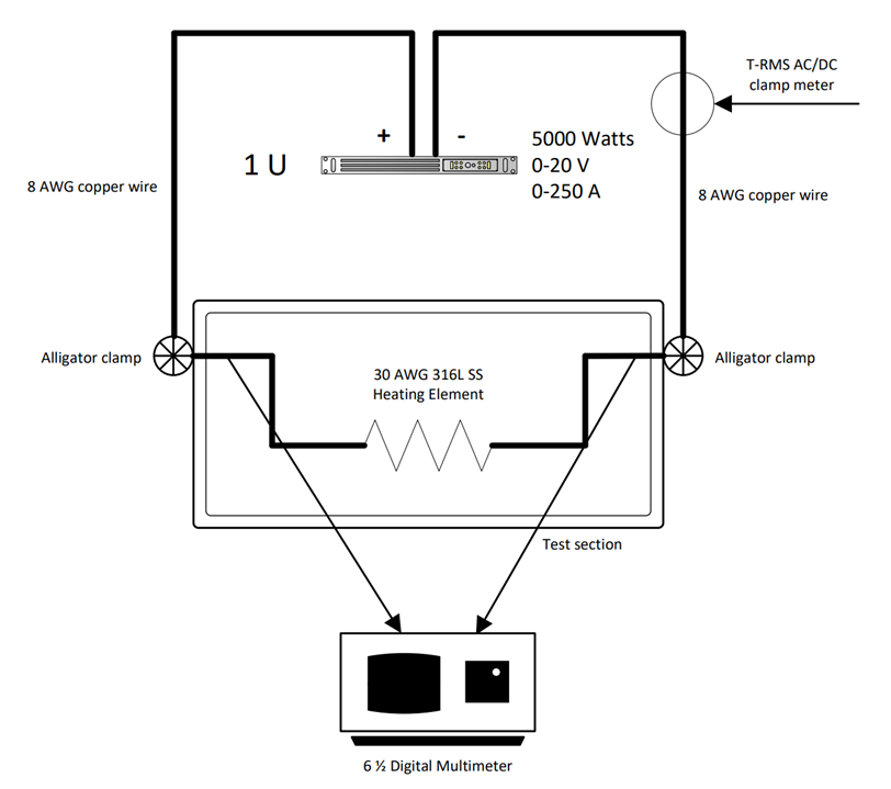
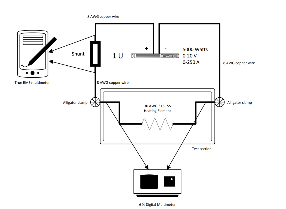
Our experimental setup consists of a 5000 Watts DC power supply (0-20V and 0-250A) connected to copper wires and then connected to a 316L Stainless Steel wire (this one stays in a water tank).

We have already run this experiment a few times, but we never got a reliable voltage measurement. Our calculated resistance for the heater in general decreases with increasing the power in the power supply, what is not true for two reasons: (1) we can observe the different regimes using a high speed-camera, and (2) increasing power means increasing the heater temperature that means increasing resistance according to the temperature x resistance relation.

In addition, our power supply display is not reliable, so we measure our system current using a clamp digital ammeter. Our voltage across the heater is measured by a 6 1/2 DMM. Can someone help me to understand what we are doing wrong?

Regards,

Bruno

  • Sign in to reply
  • Cancel

Top Replies

  • Jan Cumps
    Jan Cumps over 3 years ago +1
    The voltage over the heater is the voltage of your power supply - the voltage drop in your copper wires. The more current you send, the more voltage is dropped in the copper leads, and the less voltage…
  • shabaz
    shabaz over 3 years ago +1
    Also, the current measurement may become inaccurate over time* (this is a guess). It might be better to find an alternate way to measure current, e.g. measuring the voltage across the wires, and the voltage…
  • brunopserrao
    brunopserrao over 3 years ago in reply to Jan Cumps +1
    Jan, Thanks for your help. I will be in the lab tomorrow and I can take some pictures of our setup. Basically we have two 8 AWG stranded copper wires connected to the positive and negative sides of the…
  • shabaz
    shabaz over 3 years ago in reply to brunopserrao

    For the first diag below, it's unclear how accurate the clamp meter is for DC. It's going to have a large error (possibly - I'm just guessing). You could try measuring a known constant value for a while, see if it drifts. 

    image

    For the second diagram below, perhaps the resistance of the wires between the alligator clamp, and the heating element, is too large. Can you measure the voltage directly across the heating element?From the photo too, it looks like you're not directly connecting the multimeter wires on the copper block, but on a length of wire (looks like maybe 25-30cm of wire at a guess on each end, which is a total of maybe 0.5 milliohm).

    image

    • Cancel
    • Vote Up 0 Vote Down
    • Sign in to reply
    • Cancel
  • brunopserrao
    brunopserrao over 3 years ago in reply to shabaz

    I can actually make the connections direct to the heating element for now (while using this open tank), but we need to be able to get those measurements through some copper wires in the future because we want to implement this under higher pressures. In summary, we will need to get the measurements using this setup in the future anyway, due to restrictions in our pressure vessel penetrations.

    • Cancel
    • Vote Up 0 Vote Down
    • Sign in to reply
    • Cancel
  • dougw
    dougw over 3 years ago in reply to brunopserrao

    I am not sure what resistance x temperature is, although you can compute a temperature coefficient of resistance (R1 - R2 / T1- T2).

    Stainless steel has a positive temperature coefficient of resistance - when it gets hotter its resistance increases.

    I assume you are calculating the resistance by measuring voltage and current (R = V / I) and also the power (P = V x I)

    To calculate resistance you need to measure voltage only across the material whose resistance you want calculate - there should be no other current carrying wire or shunt in this voltage measurement and the meter should not be grounded. To calculate current you measure voltage across a shunt that is carrying all the current. To calculate power, measure voltage across the load and current though the load.

    There would seem to be some little mistake in how / where you are measuring voltage and calculating current and resistance.

    • Cancel
    • Vote Up 0 Vote Down
    • Sign in to reply
    • Cancel
  • dougw
    dougw over 3 years ago in reply to brunopserrao

    If you want to reduce the effect of the copper wire, use heavier gage wire.

    • Cancel
    • Vote Up 0 Vote Down
    • Sign in to reply
    • Cancel
  • brunopserrao
    brunopserrao over 3 years ago

    I tried the last suggestion to measure the voltage across the heating element (30 AWG 316L SS wire) only. At the same time, we took voltage measurements on three other points in the system: (1) between the two terminals of the power supply (positive and negative), (2) in the positive side only (between the positive terminal and the positive side of the heating element), and (3) in the negative side only (between the negative terminal and the negative side of the heating element.

    Then, the total voltage across the power supply (measurement 1) should be equal to the sum of the other three measurements. Based on that we observed the following:

    (1) The voltage measurements across the terminals (total) and across the positive side showed a stable behavior (measurements do not vary much).

    (2) The voltage measurements across the negative side and across the heating element showed an unstable behavior (measurements vary considerably).

    (3) The negative side copper block in the test section was generating a big amount of bubbles compared with the positive side copper block. That means the negative side of our system is getting hotter than our positive side.

    Note 1: Based on (2) and (3), we believe the unstable behavior happens because both, the negative copper block (part of the negative side section) and the 316L SS wire, are transferring more heat to the water than the positive side. That make sense for me if we think the electrons move from the negative to the positive terminals (electrons move in the opposite direction of the current flow). That means the power supply is providing power to the system from the negative to the positive terminals, across our system. Hence, the negative side gets hotter and most of the heat is transferred to the tank  through the copper block (due to the temperature difference between this copper block and the water) and the SS wire (since its temperature increases much faster than the copper blocks). Then, just a small portion of the power actually reaches and is released in the positive side.

    Note 2: Based on (2), we believe the instability observed in the measurements means those two section's voltages are balancing each other. That happens because the bubbles coming out of the copper block and the heating element help to cool down those parts, according to the pool boiling curve and bubble dynamics. According to bubble dynamics, when a single bubble (hot bubble) departs from a surface, it takes that heat out of the surface and the water comes in contact with the surface at this spot, increasing the heat transfer mechanisms there.

    Please give me some comments/feedbacks on the above discussion.

    • Cancel
    • Vote Up 0 Vote Down
    • Sign in to reply
    • Cancel
  • dougw
    dougw over 3 years ago in reply to brunopserrao

    If you are using bare metal, some of the current will flow through the water and not the wire.

    • Cancel
    • Vote Up 0 Vote Down
    • Sign in to reply
    • Cancel
  • dougw
    dougw over 3 years ago in reply to brunopserrao

    If one end of the wire is getting hotter, it may be due to a poor connection. With this much current, a little extra impedance at the connection will cause significant heat. Alligator clips don't provide much contact area - for a good connection, you need more total contact area than the cross-sectional area of the wire. Contact means direct metal-to-metal contact - no air or water gaps. This can be quite a problem since many connectors do not meet this criterion.

    • Cancel
    • Vote Up 0 Vote Down
    • Sign in to reply
    • Cancel
<
element14 Community

element14 is the first online community specifically for engineers. Connect with your peers and get expert answers to your questions.

  • Members
  • Learn
  • Technologies
  • Challenges & Projects
  • Products
  • Store
  • About Us
  • Feedback & Support
  • FAQs
  • Terms of Use
  • Privacy Policy
  • Legal and Copyright Notices
  • Sitemap
  • Cookies

An Avnet Company © 2026 Premier Farnell Limited. All Rights Reserved.

Premier Farnell Ltd, registered in England and Wales (no 00876412), registered office: Farnell House, Forge Lane, Leeds LS12 2NE.

ICP 备案号 10220084.

Follow element14

  • X
  • Facebook
  • linkedin
  • YouTube