element14 Community
element14 Community
    Register Log In
  • Site
  • Search
  • Log In Register
  • Community Hub
    Community Hub
    • What's New on element14
    • Feedback and Support
    • Benefits of Membership
    • Personal Blogs
    • Members Area
    • Achievement Levels
  • Learn
    Learn
    • Ask an Expert
    • eBooks
    • element14 presents
    • Learning Center
    • Tech Spotlight
    • STEM Academy
    • Webinars, Training and Events
    • Learning Groups
  • Technologies
    Technologies
    • 3D Printing
    • FPGA
    • Industrial Automation
    • Internet of Things
    • Power & Energy
    • Sensors
    • Technology Groups
  • Challenges & Projects
    Challenges & Projects
    • Design Challenges
    • element14 presents Projects
    • Project14
    • Arduino Projects
    • Raspberry Pi Projects
    • Project Groups
  • Products
    Products
    • Arduino
    • Avnet & Tria Boards Community
    • Dev Tools
    • Manufacturers
    • Multicomp Pro
    • Product Groups
    • Raspberry Pi
    • RoadTests & Reviews
  • About Us
  • Store
    Store
    • Visit Your Store
    • Choose another store...
      • Europe
      •  Austria (German)
      •  Belgium (Dutch, French)
      •  Bulgaria (Bulgarian)
      •  Czech Republic (Czech)
      •  Denmark (Danish)
      •  Estonia (Estonian)
      •  Finland (Finnish)
      •  France (French)
      •  Germany (German)
      •  Hungary (Hungarian)
      •  Ireland
      •  Israel
      •  Italy (Italian)
      •  Latvia (Latvian)
      •  
      •  Lithuania (Lithuanian)
      •  Netherlands (Dutch)
      •  Norway (Norwegian)
      •  Poland (Polish)
      •  Portugal (Portuguese)
      •  Romania (Romanian)
      •  Russia (Russian)
      •  Slovakia (Slovak)
      •  Slovenia (Slovenian)
      •  Spain (Spanish)
      •  Sweden (Swedish)
      •  Switzerland(German, French)
      •  Turkey (Turkish)
      •  United Kingdom
      • Asia Pacific
      •  Australia
      •  China
      •  Hong Kong
      •  India
      • Japan
      •  Korea (Korean)
      •  Malaysia
      •  New Zealand
      •  Philippines
      •  Singapore
      •  Taiwan
      •  Thailand (Thai)
      • Vietnam
      • Americas
      •  Brazil (Portuguese)
      •  Canada
      •  Mexico (Spanish)
      •  United States
      Can't find the country/region you're looking for? Visit our export site or find a local distributor.
  • Translate
  • Profile
  • Settings
Experts, Learning and Guidance
  • Technologies
  • More
Experts, Learning and Guidance
Ask an Expert Forum Can you help identify this symbol?
  • Blog
  • Forum
  • Documents
  • Leaderboard
  • Files
  • Members
  • Mentions
  • Sub-Groups
  • Tags
  • More
  • Cancel
  • New
Join Experts, Learning and Guidance to participate - click to join for free!
Actions
  • Share
  • More
  • Cancel
Forum Thread Details
  • State Not Answered
  • Replies 10 replies
  • Subscribers 302 subscribers
  • Views 1769 views
  • Users 0 members are here
Related
See a helpful answer?

Be sure to click 'more' and select 'suggest as answer'!

If you're the thread creator, be sure to click 'more' then 'Verify as Answer'!

Can you help identify this symbol?

opalko
opalko over 3 years ago

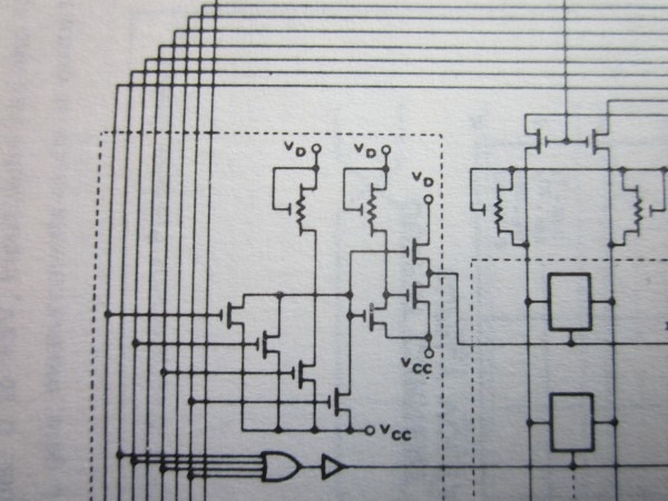
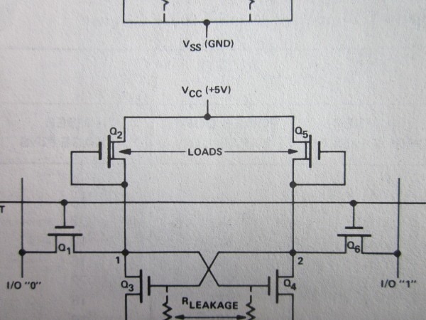
As part of an encoder chip for the keyboard on an Apple II Plus I came across this symbol in the schematic that I can't identify. Any idea what this is?

Thanks

Robert Opalko

image

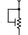
Here is where I clipped it from (also note the one on the other side denoted "ØP"??)

image

  • Sign in to reply
  • Cancel

Top Replies

  • jc2048
    jc2048 over 3 years ago in reply to shabaz +5
    Having both a weak pull-up and a stronger one that gets enabled when it's needed (by a clock phase) was probably a way to get the chip power consumption down a bit. I've seen the symbol elsewhere in…
  • jc2048
    jc2048 over 3 years ago in reply to jc2048 +5
    Here's another example of the symbol's use. This is the internal schematic of a Signetics 2501 SRAM from a 1975 datasheet. They've drawn it a bit more like the usual MFET symbol. Intel preferred this…
  • scottiebabe
    scottiebabe over 3 years ago +4
    Best guess is depletion mode nmos logic, but I'm not 100% certain. Take care
  • colporteur
    0 colporteur over 3 years ago

    I would go with a variable resistor but I do get some confusion by having a second similar component shown without the wiper connected. 0P means zero potentiometer or a resistor. Guessing mind you. 

    • Cancel
    • Vote Up +1 Vote Down
    • Sign in to reply
    • Verify Answer
    • Cancel
  • scottiebabe
    0 scottiebabe over 3 years ago

    Best guess is depletion mode nmos logic, but I'm not 100% certain. Take care 

    • Cancel
    • Vote Up +4 Vote Down
    • Sign in to reply
    • Verify Answer
    • Cancel
  • phoenixcomm
    0 phoenixcomm over 3 years ago

    Good luck, is it a restive keyboard?

    • Cancel
    • Vote Up +2 Vote Down
    • Sign in to reply
    • Verify Answer
    • Cancel
  • dougw
    0 dougw over 3 years ago

    This looks a schematic of circuitry internal to a chip and it looks like these could be substrate resistances. Note the connection is to VGG.

    I seem to recall seeing this symbol eons ago, but it was before I was fully sentient, so all I can recall is the visual.

    • Cancel
    • Vote Up +1 Vote Down
    • Sign in to reply
    • Verify Answer
    • Cancel
  • shabaz
    0 shabaz over 3 years ago

    It might just be a FET of different construction/dimensions, perhaps used in place of a resistor (normal resistors take up a lot of real-estate on a chip), so perhaps they invented that symbol. Although they violate that concept by using the device as a FET when they connected the phiP and phiIP (on mobile, don't know how to draw the Phi symbol) as inputs to a couple of the gates. Anyway, perhaps they are lower-performance FETs basically. 

    All my comment above is pure speculation however..

    • Cancel
    • Vote Up 0 Vote Down
    • Sign in to reply
    • Verify Answer
    • Cancel
  • dougw
    0 dougw over 3 years ago in reply to shabaz

    φ is one of the special characters under the insert menu. Does the mobile view not have this menu?

    • Cancel
    • Vote Up 0 Vote Down
    • Sign in to reply
    • Verify Answer
    • Cancel
  • shabaz
    0 shabaz over 3 years ago in reply to dougw

    No idea. It was quicker to respond as above than to start clicking on tiny menus/icons.

    I don't know when I'll ever absolutely need to type such characters while on mobile except once in a blue moon, so to me that didn't seem interesting to investigate.

    • Cancel
    • Vote Up 0 Vote Down
    • Sign in to reply
    • Verify Answer
    • Cancel
  • shabaz
    0 shabaz over 3 years ago in reply to shabaz

    Google'd a bit, and found this photo/diagram from Ken Shirriff's blogs showing an NMOS gate:

    image

    As can be seen in the photo, the gate is composed of two devices, the right side looking similar but slightly different, because that's a different FET (DMOS FET).

    In the photo, the right side FET has it's gate connected to 'out' rather than +5V, but other than that, no real difference to what the Apple schematic shows. So I think the symbol they're using happens to kind-of look like a resistor because that's what they are using the device as. 

    • Cancel
    • Vote Up +3 Vote Down
    • Sign in to reply
    • Verify Answer
    • Cancel
  • jc2048
    0 jc2048 over 3 years ago in reply to shabaz

    Having both a weak pull-up and a stronger one that gets enabled when it's needed (by a clock phase) was probably a way to get the chip power consumption down a bit.

    I've seen the symbol elsewhere in material about chip design, so I don't think it's unique to Apple.

    • Cancel
    • Vote Up +5 Vote Down
    • Sign in to reply
    • Verify Answer
    • Cancel
  • jc2048
    0 jc2048 over 3 years ago in reply to jc2048

    Here's another example of the symbol's use. This is the internal schematic of a Signetics 2501 SRAM from a 1975 datasheet. They've drawn it a bit more like the usual MFET symbol.

    image

    Intel preferred this, where they've simply shown where the implanted channel for the depletion device sits. This is from an application note explaining how the SRAM cells worked.

    image

    • Cancel
    • Vote Up +5 Vote Down
    • Sign in to reply
    • Verify Answer
    • Cancel
element14 Community

element14 is the first online community specifically for engineers. Connect with your peers and get expert answers to your questions.

  • Members
  • Learn
  • Technologies
  • Challenges & Projects
  • Products
  • Store
  • About Us
  • Feedback & Support
  • FAQs
  • Terms of Use
  • Privacy Policy
  • Legal and Copyright Notices
  • Sitemap
  • Cookies

An Avnet Company © 2025 Premier Farnell Limited. All Rights Reserved.

Premier Farnell Ltd, registered in England and Wales (no 00876412), registered office: Farnell House, Forge Lane, Leeds LS12 2NE.

ICP 备案号 10220084.

Follow element14

  • X
  • Facebook
  • linkedin
  • YouTube