element14 Community
element14 Community
    Register Log In
  • Site
  • Search
  • Log In Register
  • Community Hub
    Community Hub
    • What's New on element14
    • Feedback and Support
    • Benefits of Membership
    • Personal Blogs
    • Members Area
    • Achievement Levels
  • Learn
    Learn
    • Ask an Expert
    • eBooks
    • element14 presents
    • Learning Center
    • Tech Spotlight
    • STEM Academy
    • Webinars, Training and Events
    • Learning Groups
  • Technologies
    Technologies
    • 3D Printing
    • FPGA
    • Industrial Automation
    • Internet of Things
    • Power & Energy
    • Sensors
    • Technology Groups
  • Challenges & Projects
    Challenges & Projects
    • Design Challenges
    • element14 presents Projects
    • Project14
    • Arduino Projects
    • Raspberry Pi Projects
    • Project Groups
  • Products
    Products
    • Arduino
    • Avnet & Tria Boards Community
    • Dev Tools
    • Manufacturers
    • Multicomp Pro
    • Product Groups
    • Raspberry Pi
    • RoadTests & Reviews
  • About Us
  • Store
    Store
    • Visit Your Store
    • Choose another store...
      • Europe
      •  Austria (German)
      •  Belgium (Dutch, French)
      •  Bulgaria (Bulgarian)
      •  Czech Republic (Czech)
      •  Denmark (Danish)
      •  Estonia (Estonian)
      •  Finland (Finnish)
      •  France (French)
      •  Germany (German)
      •  Hungary (Hungarian)
      •  Ireland
      •  Israel
      •  Italy (Italian)
      •  Latvia (Latvian)
      •  
      •  Lithuania (Lithuanian)
      •  Netherlands (Dutch)
      •  Norway (Norwegian)
      •  Poland (Polish)
      •  Portugal (Portuguese)
      •  Romania (Romanian)
      •  Russia (Russian)
      •  Slovakia (Slovak)
      •  Slovenia (Slovenian)
      •  Spain (Spanish)
      •  Sweden (Swedish)
      •  Switzerland(German, French)
      •  Turkey (Turkish)
      •  United Kingdom
      • Asia Pacific
      •  Australia
      •  China
      •  Hong Kong
      •  India
      • Japan
      •  Korea (Korean)
      •  Malaysia
      •  New Zealand
      •  Philippines
      •  Singapore
      •  Taiwan
      •  Thailand (Thai)
      • Vietnam
      • Americas
      •  Brazil (Portuguese)
      •  Canada
      •  Mexico (Spanish)
      •  United States
      Can't find the country/region you're looking for? Visit our export site or find a local distributor.
  • Translate
  • Profile
  • Settings
Experts, Learning and Guidance
  • Technologies
  • More
Experts, Learning and Guidance
Ask an Expert Forum Extra eyes on ESP32 Reflections ThingTwo main board?
  • Blog
  • Forum
  • Documents
  • Leaderboard
  • Files
  • Members
  • Mentions
  • Sub-Groups
  • Tags
  • More
  • Cancel
  • New
Join Experts, Learning and Guidance to participate - click to join for free!
Actions
  • Share
  • More
  • Cancel
Forum Thread Details
  • Replies 11 replies
  • Subscribers 303 subscribers
  • Views 2448 views
  • Users 0 members are here
  • board
  • ask_an_expert
  • arduino
  • question
Related
See a helpful answer?

Be sure to click 'more' and select 'suggest as answer'!

If you're the thread creator, be sure to click 'more' then 'Verify as Answer'!

Extra eyes on ESP32 Reflections ThingTwo main board?

frankcohen
frankcohen over 3 years ago

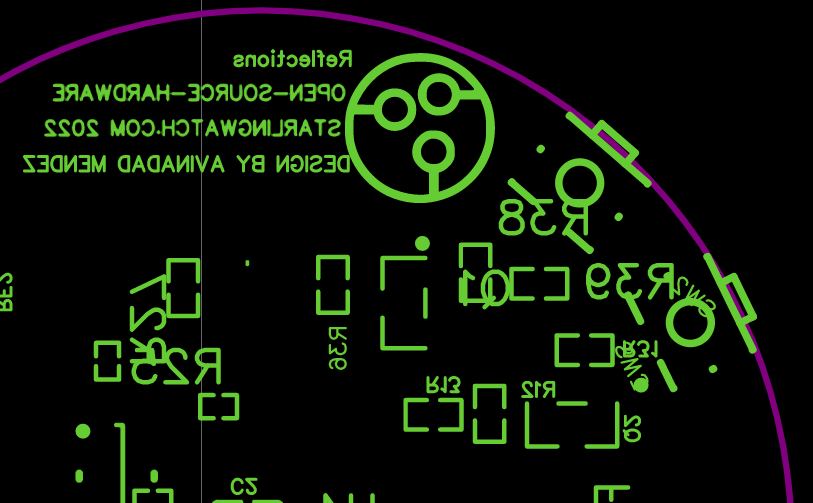
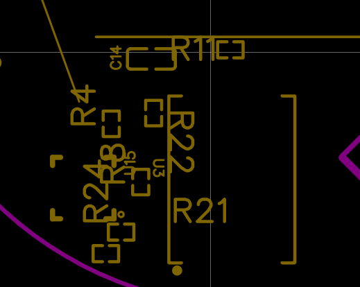
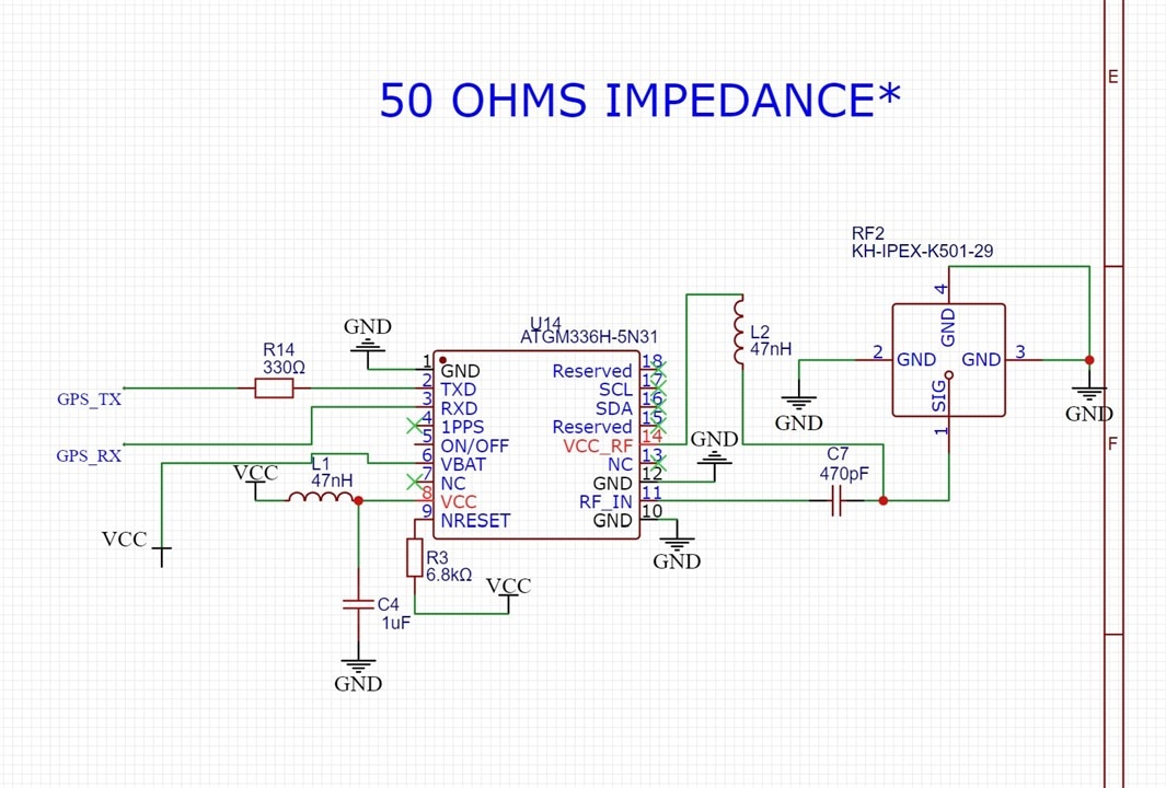
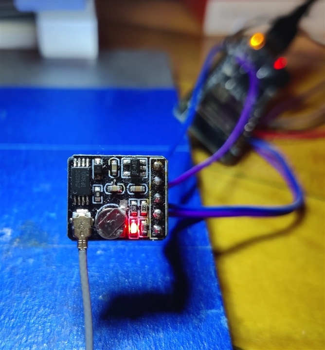
Hi 14-ers, I'm seeking your help to review the third revision to the Reflections open-source hardware main board, codenamed ThingTwo. It's an ESP32-S3 in a 34 mm round double-sided board. This is my first-time to produce a hardware/software project. I'm excited and nervous. I would be glad for your eyes on the design: Identify mistakes, limitations, and poor design choices. And, make changes to improve it.

Schematic, layout, and BOM are at:

oshwlab.com/.../Reflections-Mainboard

The main repository is at github.com/.../ReflectionsOS.

I produced this to make mobile storytelling experiences. I am distributing the design under a free open-source GPL v3 software license.

Thanks for considering my ask.

-Frank

  • Sign in to reply
  • Cancel

Top Replies

  • fmilburn
    fmilburn over 3 years ago +2
    From a quick look at your github link it appears you have working hardware in your most recent iteration so congratulations. What issues did you encounter and are there any still troubling you?
  • shabaz
    shabaz over 3 years ago +2
    Hi, The silkscreen makes it hard to see what's going on. Some text is sub-millimeter (and may not be readable on the physical board) and some text is many millimeters high, and overlapping with other…
  • fmilburn
    fmilburn over 3 years ago +2
    I found the schematic difficult to follow as well. For example, below is the GPS which is labelled "50 OHMS IMPEDANCE" instead of GPS. I had to look up the part number to see what it was. I was interested…
  • fmilburn
    fmilburn over 3 years ago

    From a quick look at your github link it appears you have working hardware in your most recent iteration so congratulations. What issues did you encounter and are there any still troubling you?  

    • Cancel
    • Vote Up +2 Vote Down
    • Sign in to reply
    • Cancel
  • frankcohen
    frankcohen over 3 years ago in reply to fmilburn

    Thanks, here are the problems we had with the rev 2 Hoober board, and the requirements for ThingTwo. These are from https://github.com/frankcohen/ReflectionsOS/blob/main/Devices/ThingTwo/ThingTwo_project_notes.md

    What went wrong in Hoober:

    • TFT display module pads used wrong pitch, the amazing Ryan Orosz of Surface Mount Solutions in Santa Clara, California created a patch cable.

    • Power-up did not work as expected, and was unneeded.

    • GPS did not work, no satellites captured.

    • NAND pads reversed.

    • Feedback from the Element14 community says we should have no components, traces, and vias under and around the ESP32 antenna array, https://bit.ly/3Od68kH

    • Power to the display cable did not work.

    • Using Adafruit Feather ESP32-S3-Mini board definition. This appears incompatible with Platform.IO and the JTAG debugger support.

    • ESP32-S3 does not reset after upload from Arduino IDE and esptool.py v3.3.1. This is a bug in the ESP32-S3 firmware. espressif/arduino-esp32#6762

    • Adafruit_DRV2605 software library does not support custom SPI pins for the Haptic feedback motor.

    • Forgot to order PCB SMT stencils from PCBway. Had new ones produced in California by Surface Mount Solutions.

    • Original PCBway order forgot to panelize the boards. Surface Mount Solutions of Santa Clara, California did the board assembly. They really like v-score instead of drilled tabs. And "north south east and west" orientation.

    • Last minute parts swaps due to out-of-stock sitatuions.

    • Pandemic forced Shanghai city quarantine, slowing parts availability.

    THINGTWO REQUIREMENTS

    ThingTwo is the 3rd revision of the Reflections main board. It is the successor to Hoober and Sox.

    ThingTwo board changes:

    • Pickup Hoober rework changes, details in https://bit.ly/3PmWc9c

    • Remove power-on/off circuit and power button.

    • Replace GPS circuit with ATGM336H module.

    • Add power-on LED.

    • Display connector pads have corrected pitch.

    • Remove traces and vias around ESP32 antenna, https://bit.ly/3Od68kH

    • Add more room around the daughter board cable pads for easier soldering.

    • Cancel
    • Vote Up +1 Vote Down
    • Sign in to reply
    • Cancel
  • shabaz
    shabaz over 3 years ago

    Hi,

    The silkscreen makes it hard to see what's going on.

    Some text is sub-millimeter (and may not be readable on the physical board) and some text is many millimeters high, and overlapping with other text and component outlines.

    You probably don't want to go smaller than ~0.9 mm text height (and ideally a bit larger, say 1mm or 1.2mm), i.e. aim for a bit larger, and if really necessary, drop down to ~0.9mm height..

    It is preferable to omit some component references if there's absolutely no way of fitting in the text, rather than overlapping with other text or outlines, or place the text elsewhere on the board and make it clear (through arrows or boxes for instance) which components it refers to.

    image

    image

    • Cancel
    • Vote Up +2 Vote Down
    • Sign in to reply
    • Cancel
  • shabaz
    shabaz over 3 years ago in reply to shabaz

    Incidentally, all of these are likely generating warnings in the software tool (EasyEDA), so the PCB designer is aware that they need to do this.

    • Cancel
    • Vote Up +1 Vote Down
    • Sign in to reply
    • Cancel
  • frankcohen
    frankcohen over 3 years ago in reply to shabaz

    Thanks! I appreciate your effort. I will clean-up the silkscreen. -Frank

    • Cancel
    • Vote Up 0 Vote Down
    • Sign in to reply
    • Cancel
  • fmilburn
    fmilburn over 3 years ago

    I found the schematic difficult to follow as well.  For example, below is the GPS which is labelled "50 OHMS IMPEDANCE" instead of GPS.  I had to look up the part number to see what it was.  I was interested in seeing what the GPS schematic looked like because the previous version was said not to work.

    GPS

    The pin marked "ON/OFF" is not connected.  I'm not familiar with this part and don't know if that is acceptable or not but it should show a connection or be marked with an X flag to indicate it has no connection.  There are several other pins like this on the schematic and the design rule checker should be issuing warnings.  Ideally the GPS would be tested / prototyped before adding to the larger project which would reduce wiring and code errors.

    Have you had a good look at the power budget?  There won't be much room for a battery and some of the components are likely to be power hungry.  

    • Cancel
    • Vote Up +2 Vote Down
    • Sign in to reply
    • Cancel
  • shabaz
    shabaz over 3 years ago in reply to fmilburn

    I feel the same as Frank, it's hard to follow, with upside-down earth symbols, and in places there were wire labels hanging off corners.

    Something's not right if this is the third iteration and it couldn't be made to work on the previous two. The very first PCB should work, albeit a few bodge wires may be needed on the first PCB. If it cannot be made to work on that first PCB (with bodge wires/cut traces and so on), it's a DEFCON 1 level situation.

    You mention the GPS didn't work, and it has been replaced with a different module. As Frank too suggests, has that been tested in a prototype? (By prototype, it means just tack wires to it if necessary, and solder it to your board). It's best to go into a PCB design with close to 100% confidence that it will all work. Unless it's a really simple design, I don't think I've ever made a PCB design without at least some prototyping, on stripboard or whatever, or (if it's easy to do so - not the case with a GPS module) simulation. 

    If the engineer can make the schematic tidy, the process of doing that may reveal issues to them. Also, a design review (where they talk it through with you - it doesn't matter if you are experienced or not, it will help the engineer discover bugs merely through talking through their design (they could talk it through to a cat if necessary! although it's best discussed to a human, so that you can ask simple questions, and you don't need to understand the response, provided it sounds like a well-reasoned response).

    • Cancel
    • Vote Up +1 Vote Down
    • Sign in to reply
    • Cancel
  • shabaz
    shabaz over 3 years ago in reply to shabaz

    Also, there's still an inner-layer ground plane around the module, and that's been discussed multiple times, so the fact that it has not been picked up as an issue, means that there has been zero design review, because that review would have been the opportunity to ask why it's still present on the third release of the board.

    • Cancel
    • Vote Up +2 Vote Down
    • Sign in to reply
    • Cancel
  • frankcohen
    frankcohen over 3 years ago in reply to fmilburn

    "For example, below is the GPS which is labelled "50 OHMS IMPEDANCE" instead of GPS. " I take your point, and well. I will work on cleaning up the silkscreen overall. And to your point about the impedance label it applies only to Pin 11 RF_IN. I'm changing the label and denoting GPS for the module.

    The Sox (rev 1) and Hoober (rev 2) GPS modules may have worked; However, the boards has so many fundamental problems - like Sox ESP32 not booting. I tested the ATGM336H-5N31 in a breadboard and it works great. It comes in a surface mount module, so much less testing and I chose it. 

    "Have you had a good look at the power budget?" Measuring current needs is coming up next week. I will report what I learn here.

    image

    • Cancel
    • Vote Up 0 Vote Down
    • Sign in to reply
    • Cancel
  • frankcohen
    frankcohen over 3 years ago in reply to shabaz

    Hi Shabaz, "Something's not right if this is the third iteration and it couldn't be made to work on the previous two." I had planned to do 3 revisions of the board (Sox, then Hoober, then ThingTwo), with reworks (cut traces, soldered wire) on each. So far that has worked well, including Hoober mounting as a hard drive and later displaying videos on the display at 10 Frames Per Second. I'm feeling good about where we are at. -Frank

    • Cancel
    • Vote Up 0 Vote Down
    • Sign in to reply
    • Cancel
>
element14 Community

element14 is the first online community specifically for engineers. Connect with your peers and get expert answers to your questions.

  • Members
  • Learn
  • Technologies
  • Challenges & Projects
  • Products
  • Store
  • About Us
  • Feedback & Support
  • FAQs
  • Terms of Use
  • Privacy Policy
  • Legal and Copyright Notices
  • Sitemap
  • Cookies

An Avnet Company © 2025 Premier Farnell Limited. All Rights Reserved.

Premier Farnell Ltd, registered in England and Wales (no 00876412), registered office: Farnell House, Forge Lane, Leeds LS12 2NE.

ICP 备案号 10220084.

Follow element14

  • X
  • Facebook
  • linkedin
  • YouTube