element14 Community
element14 Community
    Register Log In
  • Site
  • Search
  • Log In Register
  • About Us
  • Community Hub
    Community Hub
    • What's New on element14
    • Feedback and Support
    • Benefits of Membership
    • Personal Blogs
    • Members Area
    • Achievement Levels
  • Learn
    Learn
    • Ask an Expert
    • eBooks
    • element14 presents
    • Learning Center
    • Tech Spotlight
    • STEM Academy
    • Webinars, Training and Events
    • Learning Groups
  • Technologies
    Technologies
    • 3D Printing
    • FPGA
    • Industrial Automation
    • Internet of Things
    • Power & Energy
    • Sensors
    • Technology Groups
  • Challenges & Projects
    Challenges & Projects
    • Design Challenges
    • element14 presents Projects
    • Project14
    • Arduino Projects
    • Raspberry Pi Projects
    • Project Groups
  • Products
    Products
    • Arduino
    • Avnet Boards Community
    • Dev Tools
    • Manufacturers
    • Multicomp Pro
    • Product Groups
    • Raspberry Pi
    • RoadTests & Reviews
  • Store
    Store
    • Visit Your Store
    • Choose another store...
      • Europe
      •  Austria (German)
      •  Belgium (Dutch, French)
      •  Bulgaria (Bulgarian)
      •  Czech Republic (Czech)
      •  Denmark (Danish)
      •  Estonia (Estonian)
      •  Finland (Finnish)
      •  France (French)
      •  Germany (German)
      •  Hungary (Hungarian)
      •  Ireland
      •  Israel
      •  Italy (Italian)
      •  Latvia (Latvian)
      •  
      •  Lithuania (Lithuanian)
      •  Netherlands (Dutch)
      •  Norway (Norwegian)
      •  Poland (Polish)
      •  Portugal (Portuguese)
      •  Romania (Romanian)
      •  Russia (Russian)
      •  Slovakia (Slovak)
      •  Slovenia (Slovenian)
      •  Spain (Spanish)
      •  Sweden (Swedish)
      •  Switzerland(German, French)
      •  Turkey (Turkish)
      •  United Kingdom
      • Asia Pacific
      •  Australia
      •  China
      •  Hong Kong
      •  India
      •  Korea (Korean)
      •  Malaysia
      •  New Zealand
      •  Philippines
      •  Singapore
      •  Taiwan
      •  Thailand (Thai)
      • Americas
      •  Brazil (Portuguese)
      •  Canada
      •  Mexico (Spanish)
      •  United States
      Can't find the country/region you're looking for? Visit our export site or find a local distributor.
  • Translate
  • Profile
  • Settings
Experts, Learning and Guidance
  • Technologies
  • More
Experts, Learning and Guidance
Ask an Expert Forum Trying to understand NFC ASK Modulation
  • Blog
  • Forum
  • Documents
  • Leaderboard
  • Files
  • Members
  • Mentions
  • Sub-Groups
  • Tags
  • More
  • Cancel
  • New
Join Experts, Learning and Guidance to participate - click to join for free!
Actions
  • Share
  • More
  • Cancel
Forum Thread Details
  • State Not Answered
  • Replies 19 replies
  • Subscribers 288 subscribers
  • Views 2921 views
  • Users 0 members are here
  • raspberry pico
  • nfc
  • nfc-a
Related
See a helpful answer?

Be sure to click 'more' and select 'suggest as answer'!

If you're the thread creator, be sure to click 'more' then 'Verify as Answer'!

Trying to understand NFC ASK Modulation

BigG
BigG over 2 years ago

According to my Google search, NFC uses ASK modulation to transmit data:

https://www.rfwireless-world.com/Tutorials/NFC-Near-Field-Communication-tutorial.html

https://www.rfwireless-world.com/Tutorials/NFC-Modulation-and-NFC-Coding.html

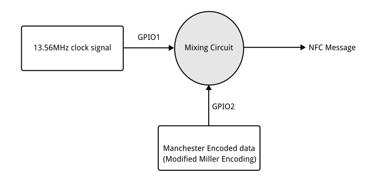
Which I have interpreted as the following where the "Mixing Circuit" includes the NFC tuned antenna and two picoFarad capacitors... but what else is needed.
image

As a non electronics engineer I am trying to work out a minimum circuit required.

Then my lofty intentions is to use a Raspberry Pi Pico to generate my clock signal using PIO and as there is also a Manchester Encoding PIO example, I will attempt to use that too.

So could this work, I wonder?

  • Sign in to reply
  • Cancel

Top Replies

  • jc2048
    jc2048 over 2 years ago +3
    I'm far from being an expert, but this is my understanding of the basic principles in case it helps (this is 20 years out of date, but the basic stuff won't have changed too much). I think I'm duplicating…
  • michaelkellett
    michaelkellett over 2 years ago +2
    This will be harder than you think ! A long time ago (2006) I did work designing antennae for MIFARE (same thing, more or less) and it's quite tricky. NXP still are fairly active in this field and…
  • scottiebabe
    scottiebabe over 2 years ago +2
    It is possible for sure, but its not really a project I would recommend taking on without an oscilloscope. So if your looking for an excuse to purchase an MXO4 scope, id say go for it ;) I am Rx/Tx…
Parents
  • BigG
    0 BigG over 2 years ago

    Thanks for the replies.

    I was inspired and curious to learn how Nordic Semiconductor do it on the nRF52 devices. Their documentation says that they emulate a NFC-A tag. Hence throwing this out to the audience to see if any other experts can offer insight.

    https://infocenter.nordicsemi.com/topic/ug_nrf52840_dk/UG/dk/hw_nfc_if.html

    (Check product specification and block diagram. Also under peripherals section NFCT):

    https://infocenter.nordicsemi.com/topic/struct_nrf52/struct/nrf52840.html

    Within the product spec is this diagram, which explains things better (to experts rather than novices like me):

    image

    When browsing on the Internet I came across this project on Hackster.io: https://www.hackster.io/sandeep-mistry/create-a-usb-microphone-with-the-raspberry-pi-pico-cc9bd5

    Under the section "How does PDM work" is a block diagram, which with a little stretch of the imagination is quite similar to the block diagrams shown on the Nordic Semiconductor website about how the nRF52 handles ASKM. Both use DMA, both use 2 pins (one for clock and one for data) and both rely on modulation techniques - obviously pulse dense is different to amplitude shift modulation but that's just the method of application.

    So, I was thinking over night that once a phone or NFC controller device activates the NFC field (I was planning to use a standard off-the-shelf NFC antenna attached to a Pico) then with some simple resonant circuitry the Raspberry Pico PIO Interrupt option could be used to sinc the clock signal and then read Manchester encoded data or send Manchester encoded data via the data pin.

    Anyway those are my brain burps so far.

    PS. I can across this document, which provides some good info too: scdn.rohde-schwarz.com/.../1MA182_5E_NFC_WHITE_PAPER.pdf

    • Cancel
    • Vote Up 0 Vote Down
    • Sign in to reply
    • Verify Answer
    • Cancel
  • shabaz
    0 shabaz over 2 years ago in reply to BigG

    Receiving the signal is different, there's the 13.56 MHz receiver in the block diagram, and that's missing from the Pico, it requires some hardware.

    if it is just ASK then normal AM demodulation can be straightforward, it may still need some amplification or limiting, and a bit of circuitry (known as a slicer) is needed to create the logic signal before you feed it into the Pico. It won't be great, this is very crude, but might work. Another approach (for any demodulation scheme) could be using SDR and DSP techniques but that too requires additional circuitry (for an example, see "sound card SDR", I wrote a project on this a while back too, most examples use the PC to do the DSP work, but it could be a microcontroller, although most people would choose a microcontroller with the right maths acceleration features, which I don't believe the Pico's RP2040 has, but I have not checked; it might still be fast enough but I don't know).

    • Cancel
    • Vote Up 0 Vote Down
    • Sign in to reply
    • Verify Answer
    • Cancel
  • BigG
    0 BigG over 2 years ago in reply to shabaz
    shabaz said:
    Another approach (for any demodulation scheme) could be using SDR and DSP techniques

    From what I can gather it is just ASK so basic circuit just capacitors/inductors and if need to amplification then amp and associated components required? Anyway, I will read your sound card SDR example as I had thought that maybe this was the way to do it.

    • Cancel
    • Vote Up +1 Vote Down
    • Sign in to reply
    • Verify Answer
    • Cancel
Reply
  • BigG
    0 BigG over 2 years ago in reply to shabaz
    shabaz said:
    Another approach (for any demodulation scheme) could be using SDR and DSP techniques

    From what I can gather it is just ASK so basic circuit just capacitors/inductors and if need to amplification then amp and associated components required? Anyway, I will read your sound card SDR example as I had thought that maybe this was the way to do it.

    • Cancel
    • Vote Up +1 Vote Down
    • Sign in to reply
    • Verify Answer
    • Cancel
Children
  • shabaz
    0 shabaz over 2 years ago in reply to BigG

    Exactly that, for ASK it could be as simple as the inductor and capacitor as your tuned circuit, and an op-amp buffer for instance (high GBW) for a bit of gain, it might not even need to be a lot of gain since the signal is close-by and large, and a diode to perform the demodulation, and a comparator circuit to extract the on/off nature of the signal that was modulated by the transmitter side. 

    • Cancel
    • Vote Up 0 Vote Down
    • Sign in to reply
    • Verify Answer
    • Cancel
element14 Community

element14 is the first online community specifically for engineers. Connect with your peers and get expert answers to your questions.

  • Members
  • Learn
  • Technologies
  • Challenges & Projects
  • Products
  • Store
  • About Us
  • Feedback & Support
  • FAQs
  • Terms of Use
  • Privacy Policy
  • Legal and Copyright Notices
  • Sitemap
  • Cookies

An Avnet Company © 2025 Premier Farnell Limited. All Rights Reserved.

Premier Farnell Ltd, registered in England and Wales (no 00876412), registered office: Farnell House, Forge Lane, Leeds LS12 2NE.

ICP 备案号 10220084.

Follow element14

  • X
  • Facebook
  • linkedin
  • YouTube