element14 Community
element14 Community
    Register Log In
  • Site
  • Search
  • Log In Register
  • About Us
  • Community Hub
    Community Hub
    • What's New on element14
    • Feedback and Support
    • Benefits of Membership
    • Personal Blogs
    • Members Area
    • Achievement Levels
  • Learn
    Learn
    • Ask an Expert
    • eBooks
    • element14 presents
    • Learning Center
    • Tech Spotlight
    • STEM Academy
    • Webinars, Training and Events
    • Learning Groups
  • Technologies
    Technologies
    • 3D Printing
    • FPGA
    • Industrial Automation
    • Internet of Things
    • Power & Energy
    • Sensors
    • Technology Groups
  • Challenges & Projects
    Challenges & Projects
    • Design Challenges
    • element14 presents Projects
    • Project14
    • Arduino Projects
    • Raspberry Pi Projects
    • Project Groups
  • Products
    Products
    • Arduino
    • Avnet Boards Community
    • Dev Tools
    • Manufacturers
    • Multicomp Pro
    • Product Groups
    • Raspberry Pi
    • RoadTests & Reviews
  • Store
    Store
    • Visit Your Store
    • Choose another store...
      • Europe
      •  Austria (German)
      •  Belgium (Dutch, French)
      •  Bulgaria (Bulgarian)
      •  Czech Republic (Czech)
      •  Denmark (Danish)
      •  Estonia (Estonian)
      •  Finland (Finnish)
      •  France (French)
      •  Germany (German)
      •  Hungary (Hungarian)
      •  Ireland
      •  Israel
      •  Italy (Italian)
      •  Latvia (Latvian)
      •  
      •  Lithuania (Lithuanian)
      •  Netherlands (Dutch)
      •  Norway (Norwegian)
      •  Poland (Polish)
      •  Portugal (Portuguese)
      •  Romania (Romanian)
      •  Russia (Russian)
      •  Slovakia (Slovak)
      •  Slovenia (Slovenian)
      •  Spain (Spanish)
      •  Sweden (Swedish)
      •  Switzerland(German, French)
      •  Turkey (Turkish)
      •  United Kingdom
      • Asia Pacific
      •  Australia
      •  China
      •  Hong Kong
      •  India
      •  Korea (Korean)
      •  Malaysia
      •  New Zealand
      •  Philippines
      •  Singapore
      •  Taiwan
      •  Thailand (Thai)
      • Americas
      •  Brazil (Portuguese)
      •  Canada
      •  Mexico (Spanish)
      •  United States
      Can't find the country/region you're looking for? Visit our export site or find a local distributor.
  • Translate
  • Profile
  • Settings
Experts, Learning and Guidance
  • Technologies
  • More
Experts, Learning and Guidance
Ask an Expert Forum Trying to understand NFC ASK Modulation
  • Blog
  • Forum
  • Documents
  • Leaderboard
  • Files
  • Members
  • Mentions
  • Sub-Groups
  • Tags
  • More
  • Cancel
  • New
Join Experts, Learning and Guidance to participate - click to join for free!
Actions
  • Share
  • More
  • Cancel
Forum Thread Details
  • State Not Answered
  • Replies 19 replies
  • Subscribers 288 subscribers
  • Views 2920 views
  • Users 0 members are here
  • raspberry pico
  • nfc
  • nfc-a
Related
See a helpful answer?

Be sure to click 'more' and select 'suggest as answer'!

If you're the thread creator, be sure to click 'more' then 'Verify as Answer'!

Trying to understand NFC ASK Modulation

BigG
BigG over 2 years ago

According to my Google search, NFC uses ASK modulation to transmit data:

https://www.rfwireless-world.com/Tutorials/NFC-Near-Field-Communication-tutorial.html

https://www.rfwireless-world.com/Tutorials/NFC-Modulation-and-NFC-Coding.html

Which I have interpreted as the following where the "Mixing Circuit" includes the NFC tuned antenna and two picoFarad capacitors... but what else is needed.

image

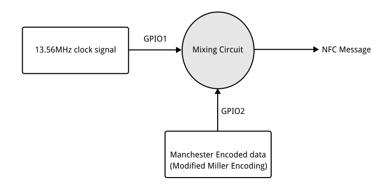
As a non electronics engineer I am trying to work out a minimum circuit required.

Then my lofty intentions is to use a Raspberry Pi Pico to generate my clock signal using PIO and as there is also a Manchester Encoding PIO example, I will attempt to use that too.

So could this work, I wonder?

  • Sign in to reply
  • Cancel

Top Replies

  • jc2048
    jc2048 over 2 years ago +3
    I'm far from being an expert, but this is my understanding of the basic principles in case it helps (this is 20 years out of date, but the basic stuff won't have changed too much). I think I'm duplicating…
  • michaelkellett
    michaelkellett over 2 years ago +2
    This will be harder than you think ! A long time ago (2006) I did work designing antennae for MIFARE (same thing, more or less) and it's quite tricky. NXP still are fairly active in this field and…
  • scottiebabe
    scottiebabe over 2 years ago +2
    It is possible for sure, but its not really a project I would recommend taking on without an oscilloscope. So if your looking for an excuse to purchase an MXO4 scope, id say go for it ;) I am Rx/Tx…
  • shabaz
    0 shabaz over 2 years ago in reply to BigG

    A slightly similar (but different) project was a heartbeat monitor strap, they transmit ASK-like pulses at a much lower frequency (5 kHz) which in theory sounds as if it should make the project easier, but with low frequencies come other issues, especially dealing with noise. I built the front end to it last year, but didn't get around to blogging it. For that, I used op-amp buffers basically, but because the signal is weak (compared to NFC, the heartbeat straps need to be monitorable from a slightly larger distance, and they run from a coin cell so not a lot of power), it needed heavy filtering to extract the signal from the noise. I didn't use SDR, but just used sharp filters. I did manage to get the signal (receivable to almost a couple of metres!, which was more than enough for its use-case) in a decent form, but other stuff got in the way and I never got to complete it. Also my pickup coil was massive : ) About the size of a coke-can.

    I don't have the schematic (I didn't create one, because I was just experimenting, and thought I was going to write the circuit down soon, but didn't) but could dig up the stripboard I created it on, would need some reverse-engineering by someone!

    • Cancel
    • Vote Up +2 Vote Down
    • Sign in to reply
    • Verify Answer
    • Cancel
  • michaelkellett
    0 michaelkellett over 2 years ago in reply to michaelkellett

    Sorry about the double post - Verint struck again - told me that neither of them had worked !

    MK

    • Cancel
    • Vote Up 0 Vote Down
    • Sign in to reply
    • Verify Answer
    • Cancel
  • scottiebabe
    0 scottiebabe over 2 years ago in reply to scottiebabe

    Well this project doesn't require anything fancy, right now I am using a 555 timer as a level translator and $10 logic analyzer! 

    I am transmitting the same source advertisement packet from a Pico

    image

    image

    Pico sending a good crc packet,

    image

    A source request

    image

    Transmitting usb-pd with the pico is quite simple, for example here is my python code for sending a goodcrc message

    def goodCRC():
        # If preamble can be 65 BMC bits then it could be done here
        # Right now, PIOSM takes care of 64 BMC bits preamble
        preamble = []#[0b1010101010]*7
        sop = [symtable['S1']]*3 + [symtable['S2']]
        header = b'\x01\x01'
        data = array.array('i',[])
        payload = header+bytes(data)
        
        crc = binascii.crc32(payload)
        payload += crc.to_bytes(4,'little')
        
        txsyms = preamble + sop
        txsyms += usbpd4b5bencode(payload)
        txsyms += [symtable['EOP'],0]
    
        pdtx(txsyms)
    

    The receive side is a bit more complicated... 

    I think it will be a helpful project for someone just wanting to experiment and learn about usb-pd signaling 

    • Cancel
    • Vote Up +2 Vote Down
    • Sign in to reply
    • Verify Answer
    • Cancel
  • shabaz
    0 shabaz over 2 years ago in reply to scottiebabe

    This looks great!

    • Cancel
    • Vote Up +1 Vote Down
    • Sign in to reply
    • Verify Answer
    • Cancel
  • scottiebabe
    0 scottiebabe over 2 years ago in reply to shabaz

    Thanks! Its been quite enjoyable experimenting with the pico, its like I'm building an my first power supply again many years later its fun try to new things!

    To send the same message as my power supply, the code was also quite simple too

    def usbpdbroadcast():
        # If preamble can be 65 BMC bits then it could be done here
        # Right now, PIOSM takes care of 64 BMC bits preamble
        preamble = []#[0b1010101010]*7
        sop = [symtable['S1']]*3 + [symtable['S2']]
        header = b'\xa1\x69'
        data = array.array('i',[0x0a01912c,0x0002d12c,0x0003c12c,0x0004b12c,0x0005a0fa,0x000640e1])
        payload = header+bytes(data)
        
        crc = binascii.crc32(payload)
        payload += crc.to_bytes(4,'little')
        
        txsyms = preamble + sop
        txsyms += usbpd4b5bencode(payload)
        txsyms += [symtable['EOP'],0]
    
        pdtx(txsyms)
        
        
    symtable = {
        0: 0b11110,
        1: 0b01001,
        2: 0b10100,
        3: 0b10101,
        4: 0b01010,
        5: 0b01011,
        6: 0b01110,
        7: 0b01111,
        8: 0b10010,
        9: 0b10011,
        10: 0b10110,
        11: 0b10111,
        12: 0b11010,
        13: 0b11011,
        14: 0b11100,
        15: 0b11101,
        'S1': 0b11000,
        'S2': 0b10001,
        'S3': 0b00110,
        'RST1': 0b00111,
        'RST2': 0b11001,
        'EOP': 0b01101}

    Hopefully soon I will have the 2 talking to each other, I think I have most of the pieces... 

    • Cancel
    • Vote Up +2 Vote Down
    • Sign in to reply
    • Verify Answer
    • Cancel
  • shabaz
    0 shabaz over 2 years ago in reply to scottiebabe

    It's great that MicroPython is being used, it's ideal for experimentation like this.

    MicroPython is not bad at all for data manipulation for protocols! I was stuck on a CRC issue a while back (I cant recall the specifics), and it was possible to find a normal Python library, and edit it slightly to function with MicroPython, so there's actually a wealth of potentially useful code that can be used with it, with a bit of tweaking occasionally.

    I hope MicroPython gets closer to real Python so that microcontroller projects benefit more from a lot of regular Python libraries.

    • Cancel
    • Vote Up +1 Vote Down
    • Sign in to reply
    • Verify Answer
    • Cancel
  • BigG
    0 BigG over 2 years ago in reply to shabaz

    I discovered this interesting project online... which uses lower frequencies etc. Schematics etc included.

    github.com/.../pico-dco

    • Cancel
    • Vote Up +1 Vote Down
    • Sign in to reply
    • Verify Answer
    • Cancel
  • jc2048
    0 jc2048 over 2 years ago

    I'm far from being an expert, but this is my understanding of the basic principles in case it helps (this is 20 years out of date, but the basic stuff won't have changed too much). I think I'm duplicating some of what others have said, but I'll leave it as it is - it's often useful to have the same things explained in different ways.

    If you are trying to build a tag, you don't need an oscillator at all. The clock signal comes to you for free from the reader.

    For all the terminology used, NFC at 13.75MHz isn't a radio system (though there are aspects that derive from radio technology and where some knowledge of design techniques and test methods are useful). There's no broadcast signal involved. It's often better to think of it being an air-cored transformer, with the reader being the primary winding and the tag/smartcard/passport/whatever being the secondary. Energy (and information) gets to a passive tag via the magnetic field that surrounds the primary coil in the reader. Although the reader coil does constitute an antenna, it's a very small one relative to the wavelength involved and is a poor radiator, and hence also a poor receiver.

    A passive tag is powered from the field by the 13.75MHz carrier being rectified and smoothed, in the same way as a low-frequency transformer PSU would work. Because it's such a high frequency, the smoothing can be quite light - no need for 20,000uF capacitors, which is fortunate if you're trying for a bank card form-factor. The clock for the tag processor comes from the 13.75MHz generated by the reader. There will also be circuitry to hold the processor in reset until the power is good enough - that's obviously necessary because, as the tag is moved into the field of the reader, you don't want a situation where it's abruptly and repeatedly starting and stopping operation, particularly if you're modifying information on the tag. If you have an active tag, you don't need to worry about the power stuff, except that you will want some indication that the tag is solidly in the field and the comms is going to be reliable.

    Signalling in the forward direction (reader to tag) is done by modulating the field that's being generated. At the tag, that will result in the amplitude of what's coming from the tag coil varying. So, to receive data, you'll need circuitry to demodulate that and get back to the signalling waveform. The modulation depth will vary quite a lot - I think it's 10% for smartcards, but I might be wrong and, in any case, you'd want your demodulator to be robust and work with practically any level. It will be a bit more tricky than a simple AM radio because the signalling rate is high (relative to the frequency of the carrier). As the signalling rate is synchronous to the carrier (I think originally it was a sixteenth, but that might have changed later in the quest to get faster data transfer) there may be cleverer ways to do the demodulation than a fast diode, smoothing with a capacitor, removal of the dc level, and then slicing (if only I was clever enough to know what they were!).

    Reverse signalling, from the tag to the reader, sounds like it would be harder but is actually much easier (that's deliberate: everything about the system was designed for a simple, cheap tag, where practically everything could be integrated into one chip). The tag can't sensibly store enough power to generate a magnetic field, like the reader does, so instead it simply loads the field a bit more for one logic level and removes the additional load for the other. The reader can sense that by the variation in power that it's having to supply to maintain the magnetic field. For a hack, that might be as simple as a MOSFET and a resistor across the tag coil. For the scheme to work well, the processor needs to take a fairly constant amount of power (over the short to medium term), but you'd want that anyway - with over-air encryption, you don't want a situation where someone gets clues as to what the tag processor is doing, whilst key handling, simply by monitoring the field. For an active tag, that isn't powered from the reader, it's not an issue, but you may find it necessary to have a dummy load to mimic what the processor would normally take.

    So you need two circuits, one to do the demodulation and one to do the modulation, and also something to tell you whether the field is stable and it's sensible to start communicating (which could probably be a byproduct of the demodulation circuit). I would suggest you use the clock (carrier) that comes from the reader to derive your signalling, so that everything stays strongly tied together: it might not matter, but there's a possibility that the reader functions better like that. Something that helps you is that the signal levels are high. The carrier output from the tag coil has to have enough amplitude to be rectified and regulated to then power a processor. Even if the processor is running on a low voltage, that immediately implies a couple of volts, so you aren't going to need all the amplification a radio needs.

    I imagine that the protocol side is quite complicated (but don't have much knowledge of that). First thing that has to happen when the reader spots tags is to determine how many tags there are in the field and start managing them, so your tag will need an ID and to know when to shout it out and when to keep quiet. It's all very carefully specified in the standards, but you'll have a lot of reading to do. As to the encryption stuff, I certainly can't help with any of that (I would assume that the relatively slow processors in tag chips have hardware assist for some of that). If you're envisioning a private system, where you develop and hence determine for yourself both the reader and the tag, you could swerve round much of that and have quite a simple system, but if you want a tag that interacts with commercial readers you're going to have to do all the detailed work of understanding the protocol side.

    Final practical point, though the coils are tuned (resonant), you won't want them to be too high a Q. The signalling sidebands are a fair way away from the carrier and if the response is too narrow the modulation will get smoothed away. The tuning isn't there for the same reason as the front end of a radio where strong selectivity is necessary to reduce the effect of adjacent channels. If you load your tag coil with some resistance, to simulate the current that would normally be taken by the processor, that might well be enough to flatten the response and give you the bandwidth you need, but this is all much easier if you have some test equipment to work with - oscilloscope and spectrum analyser.

    • Cancel
    • Vote Up +3 Vote Down
    • Sign in to reply
    • Verify Answer
    • Cancel
  • BigG
    0 BigG over 2 years ago in reply to jc2048

    Wow thanks. This is pitched at my level.

    I now understand a little bit more about what's involved and thankfully it seems I stumbled a bit further in the right direction... I've been reading up (watching some YT videos) on I/Q signals... https://www.youtube.com/watch?v=h_7d-m1ehoY

    • Cancel
    • Vote Up +1 Vote Down
    • Sign in to reply
    • Verify Answer
    • Cancel
<
element14 Community

element14 is the first online community specifically for engineers. Connect with your peers and get expert answers to your questions.

  • Members
  • Learn
  • Technologies
  • Challenges & Projects
  • Products
  • Store
  • About Us
  • Feedback & Support
  • FAQs
  • Terms of Use
  • Privacy Policy
  • Legal and Copyright Notices
  • Sitemap
  • Cookies

An Avnet Company © 2025 Premier Farnell Limited. All Rights Reserved.

Premier Farnell Ltd, registered in England and Wales (no 00876412), registered office: Farnell House, Forge Lane, Leeds LS12 2NE.

ICP 备案号 10220084.

Follow element14

  • X
  • Facebook
  • linkedin
  • YouTube