element14 Community
element14 Community
    Register Log In
  • Site
  • Search
  • Log In Register
  • Community Hub
    Community Hub
    • What's New on element14
    • Feedback and Support
    • Benefits of Membership
    • Personal Blogs
    • Members Area
    • Achievement Levels
  • Learn
    Learn
    • Ask an Expert
    • eBooks
    • element14 presents
    • Learning Center
    • Tech Spotlight
    • STEM Academy
    • Webinars, Training and Events
    • Learning Groups
  • Technologies
    Technologies
    • 3D Printing
    • FPGA
    • Industrial Automation
    • Internet of Things
    • Power & Energy
    • Sensors
    • Technology Groups
  • Challenges & Projects
    Challenges & Projects
    • Design Challenges
    • element14 presents Projects
    • Project14
    • Arduino Projects
    • Raspberry Pi Projects
    • Project Groups
  • Products
    Products
    • Arduino
    • Avnet & Tria Boards Community
    • Dev Tools
    • Manufacturers
    • Multicomp Pro
    • Product Groups
    • Raspberry Pi
    • RoadTests & Reviews
  • About Us
  • Store
    Store
    • Visit Your Store
    • Choose another store...
      • Europe
      •  Austria (German)
      •  Belgium (Dutch, French)
      •  Bulgaria (Bulgarian)
      •  Czech Republic (Czech)
      •  Denmark (Danish)
      •  Estonia (Estonian)
      •  Finland (Finnish)
      •  France (French)
      •  Germany (German)
      •  Hungary (Hungarian)
      •  Ireland
      •  Israel
      •  Italy (Italian)
      •  Latvia (Latvian)
      •  
      •  Lithuania (Lithuanian)
      •  Netherlands (Dutch)
      •  Norway (Norwegian)
      •  Poland (Polish)
      •  Portugal (Portuguese)
      •  Romania (Romanian)
      •  Russia (Russian)
      •  Slovakia (Slovak)
      •  Slovenia (Slovenian)
      •  Spain (Spanish)
      •  Sweden (Swedish)
      •  Switzerland(German, French)
      •  Turkey (Turkish)
      •  United Kingdom
      • Asia Pacific
      •  Australia
      •  China
      •  Hong Kong
      •  India
      • Japan
      •  Korea (Korean)
      •  Malaysia
      •  New Zealand
      •  Philippines
      •  Singapore
      •  Taiwan
      •  Thailand (Thai)
      • Vietnam
      • Americas
      •  Brazil (Portuguese)
      •  Canada
      •  Mexico (Spanish)
      •  United States
      Can't find the country/region you're looking for? Visit our export site or find a local distributor.
  • Translate
  • Profile
  • Settings
Experts, Learning and Guidance
  • Technologies
  • More
Experts, Learning and Guidance
Ask an Expert Forum LT8361 voltage doubler won't start under load .....HELP Please!
  • Blog
  • Forum
  • Documents
  • Leaderboard
  • Files
  • Members
  • Mentions
  • Sub-Groups
  • Tags
  • More
  • Cancel
  • New
Join Experts, Learning and Guidance to participate - click to join for free!
Actions
  • Share
  • More
  • Cancel
Forum Thread Details
  • State Not Answered
  • Replies 8 replies
  • Subscribers 302 subscribers
  • Views 1672 views
  • Users 0 members are here
Related
See a helpful answer?

Be sure to click 'more' and select 'suggest as answer'!

If you're the thread creator, be sure to click 'more' then 'Verify as Answer'!

LT8361 voltage doubler won't start under load .....HELP Please!

davebullockmbe
davebullockmbe over 2 years ago

Hi,

Hi experts,

I need some SMPSU expert help using an LT8361 as a voltage doubler please.

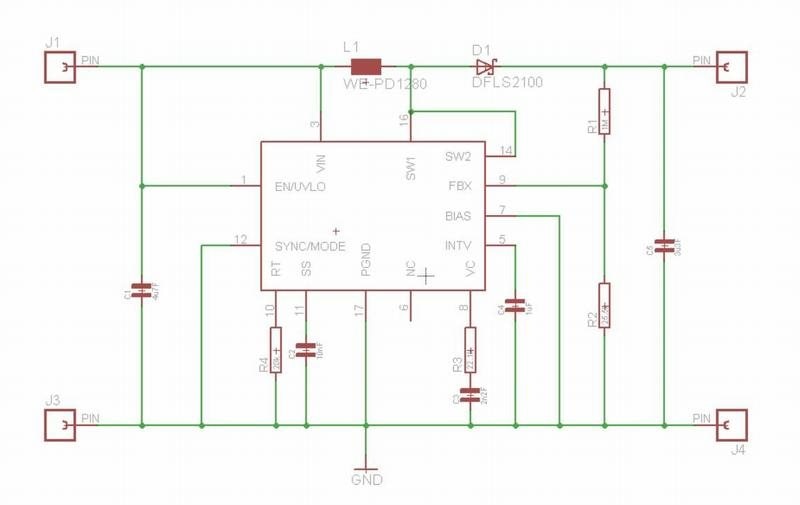
Hi, I have been using the LT8361 as a +90V power supply stepping up from 12V for several years. (schematic attached below).
My application has a load of less than 10mA and with this design the power supply will start up with or without load every time. 
I now have the need to generate 120V and as the LT8361 doesn't support this voltage, (100V max) the obvious solution is to use it as a voltage doubler.
I spotted that this had been published as a -150V supply in an Analog application. (so surely it was tried and tested here) 
https://ez.analog.com/power/f/q-a/112621/searching-for-an-inverting-converter-solution/336141

  
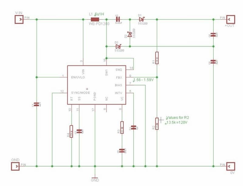
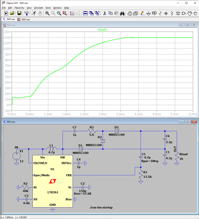
So I generated a similar design but for +120V (attached below)
The design works fine and the regulation is very good as I only need a few milliamps at 120V.
The problem is that whilst my original +90V LT8361 design will start up when (anywhere between +7V and +12V) is applied IMMEDIATELY. 
The Voltage doubling circuit will only start when the 12V supply is slowly ramped up from zero under load.
ie. applying 12V immediately the LT8361 doesn't start.  (even with a load as low as 3mA).
(it starts every time with no load BTW!)

I initially thought that the IC was detecting too high a starting current and was going into overload shutdown.
I increased the Slow Start capacitor to 0.22uF but this made no difference.
I have tried reducing the value of C5/C6 (both output caps) down to 0.1uF each and the LT8361 still will NOT start under load which seems to suggest it isn't 'inrush' current into the output capacitors?
I tried taking the voltage feedback point from the junction of C5/C6 instead of the Vout in case it was taking too long for the FBX input to see sufficient voltage thus going into a LVO scenario.
I reduced the 1M to 510K to keep the voltage division correct. As expected the Vout regulation was poorer but the LT8361 still refused to start under load!
I also tried increasing the value of C7 in case output capacitor C6 wasn't charging fast enough at switch on thus creating a UVLO situation.
Again this made NO difference.

I have two of these boards assembled and both exhibit the same problem.
I need some help from a more experienced SMPSU expert...PLEASE

Thanks in anticipation
Dave
Dave 
imageimage

  • Sign in to reply
  • Cancel

Top Replies

  • michaelkellett
    michaelkellett over 2 years ago +3
    It can be done: I think a transformer would be a much better solution than the cap and diode charge pump. Before you make this check that you are happy with the currents in the 8361 switch. You…
  • davebullockmbe
    davebullockmbe over 2 years ago in reply to michaelkellett +3
    Hi Michael, You are a genius :-) Your R3 in that position has cured my issue thankyou! I had tried series resistors in both D1 and D2's cathodes to no avail, I never thought of trying it in series…
  • michaelkellett
    michaelkellett over 2 years ago +2
    Have you tried to simulate your circuit in LTSpice. If not then I very strongly siggest that you do - it will give a great deal more insight as to why it isn't working - or maybe show you that is should…
Parents
  • michaelkellett
    0 michaelkellett over 2 years ago

    It can be done:

    image

    I think a transformer would be a much better solution than the cap and diode charge pump.

    Before you make this check that you are happy with the currents in the 8361 switch.

    You could tweak component values a bit more, and if 12mA isn't enough you'll really struggle.

    MK

    • Cancel
    • Vote Up +3 Vote Down
    • Sign in to reply
    • Verify Answer
    • Cancel
  • davebullockmbe
    0 davebullockmbe over 2 years ago in reply to michaelkellett

    Hi Michael,

    You are a genius :-)
    Your R3 in that position has cured my issue thankyou!

    I had tried series resistors in both D1 and D2's cathodes to no avail, I never thought of trying it in series with C7.
    I just lifted off the SMD cap and soldered it back 'on end' then soldered a 10 Ohm (again 'on end') on the vacated C7 pad and linked them together in free air with 'mod wire'.
    With all my original component values the LT8361 starts every time with a 4k7 Ohm load supplying 25mA which is 5 times more than I need.
    Hopefully I can fit this modification on my original pcb without having to have them re-made.


    Thank you Michael (and dougw) for your true gentlemanly spirit in finding time to help me with this problem, it is gratefully appreciated :-)
    Dave

    • Cancel
    • Vote Up +3 Vote Down
    • Sign in to reply
    • Verify Answer
    • Cancel
Reply
  • davebullockmbe
    0 davebullockmbe over 2 years ago in reply to michaelkellett

    Hi Michael,

    You are a genius :-)
    Your R3 in that position has cured my issue thankyou!

    I had tried series resistors in both D1 and D2's cathodes to no avail, I never thought of trying it in series with C7.
    I just lifted off the SMD cap and soldered it back 'on end' then soldered a 10 Ohm (again 'on end') on the vacated C7 pad and linked them together in free air with 'mod wire'.
    With all my original component values the LT8361 starts every time with a 4k7 Ohm load supplying 25mA which is 5 times more than I need.
    Hopefully I can fit this modification on my original pcb without having to have them re-made.


    Thank you Michael (and dougw) for your true gentlemanly spirit in finding time to help me with this problem, it is gratefully appreciated :-)
    Dave

    • Cancel
    • Vote Up +3 Vote Down
    • Sign in to reply
    • Verify Answer
    • Cancel
Children
  • michaelkellett
    0 michaelkellett over 2 years ago in reply to davebullockmbe

    Happy to help - broken up a long day of tedious code debugging !

    MK

    • Cancel
    • Vote Up 0 Vote Down
    • Sign in to reply
    • Verify Answer
    • Cancel
element14 Community

element14 is the first online community specifically for engineers. Connect with your peers and get expert answers to your questions.

  • Members
  • Learn
  • Technologies
  • Challenges & Projects
  • Products
  • Store
  • About Us
  • Feedback & Support
  • FAQs
  • Terms of Use
  • Privacy Policy
  • Legal and Copyright Notices
  • Sitemap
  • Cookies

An Avnet Company © 2025 Premier Farnell Limited. All Rights Reserved.

Premier Farnell Ltd, registered in England and Wales (no 00876412), registered office: Farnell House, Forge Lane, Leeds LS12 2NE.

ICP 备案号 10220084.

Follow element14

  • X
  • Facebook
  • linkedin
  • YouTube