The HV converter require 24V power supply and some analog voltage signals. I connect two 0~10V voltage signals to the pin of HV converter, 10HVA24-N1. However what I get from the output of HVA is 0V. Is there any thing wrong with my wiring?


Be sure to click 'more' and select 'suggest as answer'!
If you're the thread creator, be sure to click 'more' then 'Verify as Answer'!
The HV converter require 24V power supply and some analog voltage signals. I connect two 0~10V voltage signals to the pin of HV converter, 10HVA24-N1. However what I get from the output of HVA is 0V. Is there any thing wrong with my wiring?


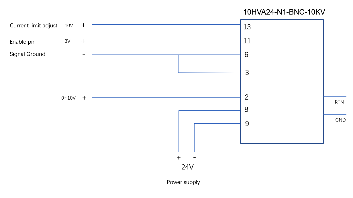
The equipment wiring diagram(2nd version) is as follows:

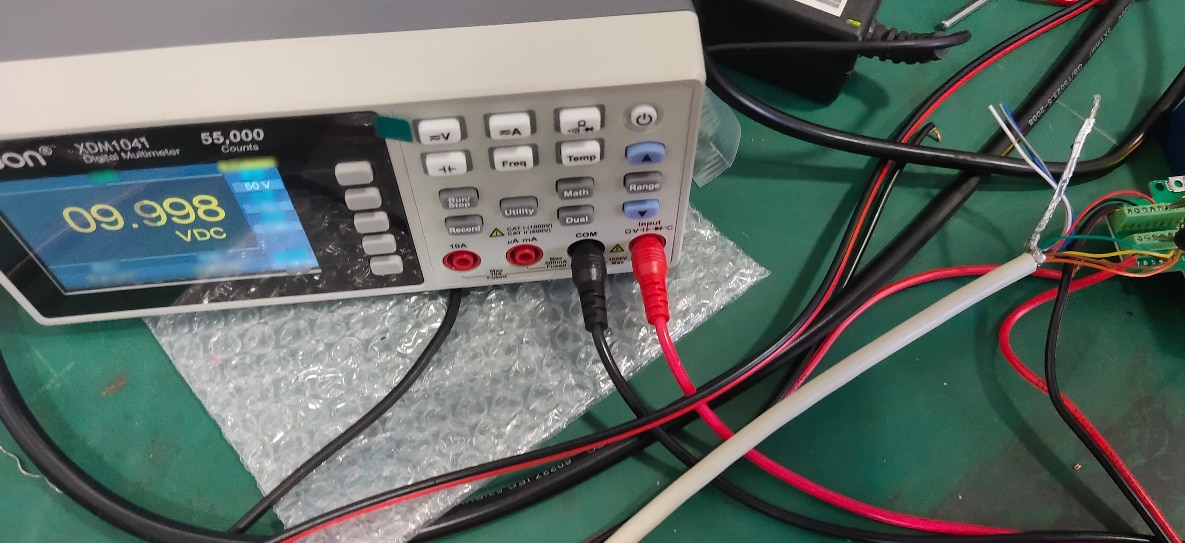
Use a voltmeter to actually measure the voltages of pin13 and pin11 relative to pin6 are 9.998V and 3.0V respectively

However, the HVA always outputs 63V, no matter what the volatge of pin2 is
However, the HVA always outputs 63V, no matter what the volatge of pin2 is
What are you using to measure your output?
100uA is not much.
I used a 1/12 divider between the output and the voltmeter to avoid damaging my voltmeter due to high voltage
It would be worth buying a proper 20kV rated high voltage probe for your meter.
You can use the ppwer supply built in voltage monitoring to check its output.
What is hapenning with power supplyLEDs when you are testing ?
MK
Value of resistors?
You mean the divider? The divider is 0.6325MΩ
The power light is on when the power supply is normal
And the 'high voltage on' led ?
MK
There are only two leds, one is the power and the other one is the enable indicator light. The enable indicator light is on when the pin11 is more than 2.4V, and it works well.
So it looks as if your power supply thinks it is working.
How is you divider working - (diagram) - its a strange co-incidence that 100uA into 0.63M would give excatly 63V.
Your power supply max output current is 100uA.
Are you trying to make it work into a 630k load ?
If you apply a 30mV voltage control signal do you get 30V on the output ?
MK