element14 Community
element14 Community
    Register Log In
  • Site
  • Search
  • Log In Register
  • Community Hub
    Community Hub
    • What's New on element14
    • Feedback and Support
    • Benefits of Membership
    • Personal Blogs
    • Members Area
    • Achievement Levels
  • Learn
    Learn
    • Ask an Expert
    • eBooks
    • element14 presents
    • Learning Center
    • Tech Spotlight
    • STEM Academy
    • Webinars, Training and Events
    • Learning Groups
  • Technologies
    Technologies
    • 3D Printing
    • FPGA
    • Industrial Automation
    • Internet of Things
    • Power & Energy
    • Sensors
    • Technology Groups
  • Challenges & Projects
    Challenges & Projects
    • Design Challenges
    • element14 presents Projects
    • Project14
    • Arduino Projects
    • Raspberry Pi Projects
    • Project Groups
  • Products
    Products
    • Arduino
    • Avnet Boards Community
    • Dev Tools
    • Manufacturers
    • Multicomp Pro
    • Product Groups
    • Raspberry Pi
    • RoadTests & Reviews
  • About Us
  • Store
    Store
    • Visit Your Store
    • Choose another store...
      • Europe
      •  Austria (German)
      •  Belgium (Dutch, French)
      •  Bulgaria (Bulgarian)
      •  Czech Republic (Czech)
      •  Denmark (Danish)
      •  Estonia (Estonian)
      •  Finland (Finnish)
      •  France (French)
      •  Germany (German)
      •  Hungary (Hungarian)
      •  Ireland
      •  Israel
      •  Italy (Italian)
      •  Latvia (Latvian)
      •  
      •  Lithuania (Lithuanian)
      •  Netherlands (Dutch)
      •  Norway (Norwegian)
      •  Poland (Polish)
      •  Portugal (Portuguese)
      •  Romania (Romanian)
      •  Russia (Russian)
      •  Slovakia (Slovak)
      •  Slovenia (Slovenian)
      •  Spain (Spanish)
      •  Sweden (Swedish)
      •  Switzerland(German, French)
      •  Turkey (Turkish)
      •  United Kingdom
      • Asia Pacific
      •  Australia
      •  China
      •  Hong Kong
      •  India
      •  Korea (Korean)
      •  Malaysia
      •  New Zealand
      •  Philippines
      •  Singapore
      •  Taiwan
      •  Thailand (Thai)
      • Americas
      •  Brazil (Portuguese)
      •  Canada
      •  Mexico (Spanish)
      •  United States
      Can't find the country/region you're looking for? Visit our export site or find a local distributor.
  • Translate
  • Profile
  • Settings
Experts, Learning and Guidance
  • Technologies
  • More
Experts, Learning and Guidance
Ask an Expert Forum Press ON - Hold OFF Latching Circuit
  • Blog
  • Forum
  • Documents
  • Leaderboard
  • Files
  • Members
  • Mentions
  • Sub-Groups
  • Tags
  • More
  • Cancel
  • New
Join Experts, Learning and Guidance to participate - click to join for free!
Actions
  • Share
  • More
  • Cancel
Forum Thread Details
  • State Not Answered
  • Replies 18 replies
  • Subscribers 287 subscribers
  • Views 4932 views
  • Users 0 members are here
Related
See a helpful answer?

Be sure to click 'more' and select 'suggest as answer'!

If you're the thread creator, be sure to click 'more' then 'Verify as Answer'!

Press ON - Hold OFF Latching Circuit

milosrasic98
milosrasic98 over 1 year ago

Hi!

For a project I'm working on, I want to turn it on and off using only a single button, but in such a way that when you press it turns ON, but for you to turn OFF the device, you need to hold it for a longer period, let's say 5 seconds for example. I was just wondering if you have any circuit ideas that you would like to propose. I've been looking online already of course, and have found one circuit that I will be trying, it's on this link:

http://www.mosaic-industries.com/embedded-systems/microcontroller-projects/electronic-circuits/push-button-switch-turn-on/latching-toggle-power-switch

Fig6

So my list of requirements for it would be:

  • Press ON
  • Hold OFF
  • (Almost) No power draw when OFF since my idea is for it to be battery-powered
  • I would love to read the state of the button with a microcontroller, but the microcontroller can't be used for the latching part, I'm already stretching the MCU thin, and I would need to add an IO expander which I would rather not do at the moment.

Thanks for any tips that you have!

Milos

  • Sign in to reply
  • Cancel

Top Replies

  • dougw
    dougw over 1 year ago +4
    This circuit only consumes leakage current when off... You might need a diode in the gate path of Q3 and a pull down resistor on Q2.
  • misaz
    misaz over 1 year ago +4
    Look at MAX16150. It includes almost all you need in tiny SOT23-6 (or WLP) package.
  • genebren
    genebren over 1 year ago +3
    I have used a power latching circuit in a lot of my designs. But instead of adding extra circuitry, I used existing circuits with a few added components. This works given that there is a need for a microprocessor…
Parents
  • shabaz
    0 shabaz over 1 year ago

    For my kitchen under-counter lighting I used an Atmel ATtiny chip, connected to a push-button, to power on/off and select several dimness levels from a single button (there may be LED flashlight chips to perform this nowadays). The kitchen circuit was not battery operated so I didn't make any effort to save energy in the microcontroller.

    Anyway this thread made me curious to see what current consumption the MSP430 would use (modern PIC might beat it, but I don't use PIC or Maxim microcontrollers, for other technical+non-technical reasons). The MSP430 chip is available in a 4x4mm package that is easy to solder (0.65mm spaced pads) and can run without any external parts (technically, just a bypass cap could be nice; but it is also helpful to add a second capacitor+resistor on the RST line, to make it easier to program in-circuit if desired).

    MSP430 is possibly no longer state-of-the-art for low-power, but it's still low (enough for years of operation, even on a coin cell).

    The part I tried (MSP430G2452) is $0.67 in 1k qty, but there's a lower Flash size version that should be cheaper (I didn't check). I used the DIP version since it plugs into the standard development board (MSP430-EXP430G2ET).

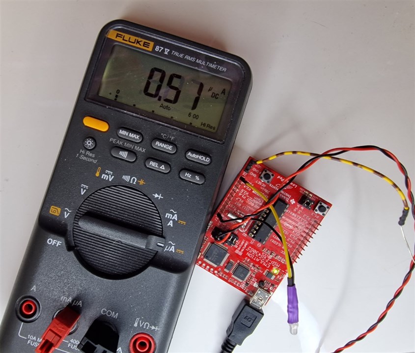
    In the setup below, the current consumption was ballpark 500nA at room temp. In theory, that chip should be able to go lower (there is a particular power mode that enables that), but that didn't work for me. I didn't spend much time on it since 500 nA is already pretty low even for some coin-cell use, and the power mode that worked is desirable for other purposes when adding features, but with the even-lower-power mode it should be possible to shave another couple of 100 nA *maybe*! But if it was that critical, I'd probably search for a more modern processor, or add more circuitry (to initially only power on the chip when the button is pressed, and then hold power to the chip with a MOSFET etc).

    image

    Here is the MSP430 push-button code if ever needed. It has separately configurable push-on and push-off delay times. It seems to function in the very limited testing I tried, but I can't guarantee it. The code isn't very pretty (I modified some earlier code I had).

    It requires a button connected between the P1.2 pin and VCC. The active-high output (to MOSFET circuitry, or enable pin of regulator, or even directly used as an output supply rail if it is low-power) is on the P2.3 pin.

    /***********************************************
     * Button Power Control
     *
     * rev 1 - shabaz - December 2023
     * This code expects a push-button wired to GPIO pin P1.2 and GND.
     * The output is on pin P2.3
     * The delays for turn-on and turn-off are separately configurable
     * (see the definitions below)
     * *********************************************/
    
    // includes
    #include <msp430.h>
    
    // ******** defines ********
    // change to suit requirements
    // times are in multiples of 10msec, so 100 means 1000 msec.
    #define PUSH_ON_INTERVAL 100
    #define PUSH_OFF_INTERVAL 100
    #define DEBOUNCE_INTERVAL 10
    
    #define PWR_ENABLE P2OUT |= (0x01 << 3)
    #define PWR_DISABLE P2OUT &= ~(0x01 << 3)
    // PUSH_BTN_B input is normally low
    #define PUSH_BTN_B_PRESSED ((P1IN & 0x04)!=0)
    #define PUSH_BTN_B_UNPRESSED ((P1IN & 0x04)==0)
    
    
    #define BTN_B_EVENT 1
    #define BTN_B_NOEVENT 0
    #define TOGGLE_NONE 0
    #define TOGGLE_WAIT_ON_DEBOUNCE 1
    #define TOGGLE_ON_REL_DEBOUNCE 2
    #define TOGGLE_ON 3
    #define TOGGLE_WAIT_OFF_DEBOUNCE 4
    #define TOGGLE_OFF_REL_DEBOUNCE 5


    // global vars
    unsigned int mtick;
    unsigned char timer_status;
    // other
    unsigned char pwrstate;
    // push-button B
    unsigned char btn_b_event;
    unsigned char toggle_state;
    
    
    // function prototypes
    
    // ********* interrupt service routines *********
    // Timer A0 interrupt service routine
    #pragma vector=TIMER0_A0_VECTOR
    __interrupt void Timer_A (void)
    {
        if (mtick < 65535) {
            mtick++;
        }
        __bic_SR_register_on_exit(LPM3_bits);
    }
    // Port 1 interrupt service routine
    #pragma vector=PORT1_VECTOR
    __interrupt void port1_isr(void)
    {
        if ((P1IFG & 0x04) != 0) {
            // P1.2 interrupt occurred
            btn_b_event = BTN_B_EVENT;
        }
        P1IFG = 0; // reset interrupt
        __bic_SR_register_on_exit(LPM3_bits);
    }
    
    // functions
    void enable_timer(void)
    {
        timer_status = 1;
        mtick=0;
        CCR0 = 120; // 120 = 10msec (approx)
        TACTL = TASSEL_1 | MC_1 | TACLR; // ACLK, upmode, and clear the counter
        CCTL0 |= CCIE; // enable CCRO interrupt
    }
    
    void disable_timer(void)
    {
        CCTL0 &= ~CCIE; // disable CCRO interrupt
        timer_status = 0;
    }
    
    // function to handle push-on and push-off functionality
    void process_btn_b(void)
    {
        switch(toggle_state) {
        case TOGGLE_NONE:
            if (btn_b_event==BTN_B_EVENT) {
                toggle_state = TOGGLE_WAIT_ON_DEBOUNCE;
                enable_timer();
            }
        break;
        case TOGGLE_WAIT_ON_DEBOUNCE:
            if(PUSH_BTN_B_PRESSED) {
                if (mtick>=PUSH_ON_INTERVAL) {
                    // button was held down long enough, so we can power up!
                    PWR_ENABLE;
                    mtick=0;
                    toggle_state = TOGGLE_ON_REL_DEBOUNCE;
                } else {
                    // continue to wait to see if the button is pressed long enough
                }
            } else {
                // button was prematurely released! abort.
                toggle_state = TOGGLE_NONE;
                disable_timer();
            }
            break;
        case TOGGLE_ON_REL_DEBOUNCE:
            if (PUSH_BTN_B_PRESSED) {
                // keep waiting for the user to release the button
            } else {
                if (mtick>=DEBOUNCE_INTERVAL) {
                    toggle_state = TOGGLE_ON;
                } else {
                    // keep waiting
                }
            }
            break;
        case TOGGLE_ON:
            // do nothing unless the button is pressed
            disable_timer();
            //if (btn_b_event==BTN_B_EVENT) {
            if (PUSH_BTN_B_PRESSED) {
                toggle_state = TOGGLE_WAIT_OFF_DEBOUNCE;
                enable_timer();
            } else {
                // do nothing, we are powered up, and no button event to power off.
            }
            break;
        case TOGGLE_WAIT_OFF_DEBOUNCE:
            if (PUSH_BTN_B_PRESSED) {
                if (mtick>=PUSH_OFF_INTERVAL) {
                    // button was held down long enough, so we can power off!
                    PWR_DISABLE;
                    mtick=0;
                    toggle_state = TOGGLE_OFF_REL_DEBOUNCE;
                } else {
                    // continue to wait to see if button is pressed long enough
                }
            } else {
                // button was prematurely released! abort back to the ON state.
                toggle_state = TOGGLE_ON;
                disable_timer();
            }
            break;
        case TOGGLE_OFF_REL_DEBOUNCE:
            if (PUSH_BTN_B_PRESSED) {
                // keep waiting for the user to release the button
            } else {
                if (mtick>=DEBOUNCE_INTERVAL) {
                    toggle_state = TOGGLE_NONE;
                    disable_timer();
                } else {
                    // keep waiting
                }
            }
        default:
            break;
        }
        btn_b_event=BTN_B_NOEVENT;
    }
    
    // ************* main function ******************
    void main (void)
    {
        WDTCTL = WDTPW | WDTHOLD; // stop watchdog timer
        BCSCTL3 = LFXT1S_2; // use VLO for ACLK
    
        // global var initialization
        mtick=0;
        timer_status = 0;
        btn_b_event = BTN_B_NOEVENT;
        toggle_state = TOGGLE_NONE;
    
    
        // input/output initialization
        P1OUT = 0;
        P2OUT = 0;
        P1DIR = 0xF8; // Set P1.3, 1.4, 1.5, 1.6, 1.7 as outputs
        P2DIR = 0x2f; // Set P2.0, 2.1, 2.2, 2.3, 2.5 as outputs
        P1REN |= 0x07; // resistor enabled for P1.0, 1.1, 1.2 (to act as pull-down)
        P2REN |= 0x10; // resistor enabled for P2.4 (to act as pull-down)
        P1IES &= ~0x04; // interrupt on low-to-high transition of P1.2
        P1IE |= 0x04; // interrupt enable for P1.2
    
        PWR_DISABLE; // start with the power disabled
    
        __bis_SR_register(GIE); // enable interrupts
    
        while(1) {
            // enter a power mode depending on if button detection or clock interrupt is needed
            if (timer_status) {
                __bis_SR_register(LPM3_bits); // enter LPM3, clock will be updated
            } else {
                __bis_SR_register(LPM3_bits); // don't know why LPM4_bits here doesn't work
            }
            process_btn_b();
            _NOP(); // set breakpoint here if desired to see operation
        }
    }


    • Cancel
    • Vote Up +3 Vote Down
    • Sign in to reply
    • Verify Answer
    • Cancel
Reply
  • shabaz
    0 shabaz over 1 year ago

    For my kitchen under-counter lighting I used an Atmel ATtiny chip, connected to a push-button, to power on/off and select several dimness levels from a single button (there may be LED flashlight chips to perform this nowadays). The kitchen circuit was not battery operated so I didn't make any effort to save energy in the microcontroller.

    Anyway this thread made me curious to see what current consumption the MSP430 would use (modern PIC might beat it, but I don't use PIC or Maxim microcontrollers, for other technical+non-technical reasons). The MSP430 chip is available in a 4x4mm package that is easy to solder (0.65mm spaced pads) and can run without any external parts (technically, just a bypass cap could be nice; but it is also helpful to add a second capacitor+resistor on the RST line, to make it easier to program in-circuit if desired).

    MSP430 is possibly no longer state-of-the-art for low-power, but it's still low (enough for years of operation, even on a coin cell).

    The part I tried (MSP430G2452) is $0.67 in 1k qty, but there's a lower Flash size version that should be cheaper (I didn't check). I used the DIP version since it plugs into the standard development board (MSP430-EXP430G2ET).

    In the setup below, the current consumption was ballpark 500nA at room temp. In theory, that chip should be able to go lower (there is a particular power mode that enables that), but that didn't work for me. I didn't spend much time on it since 500 nA is already pretty low even for some coin-cell use, and the power mode that worked is desirable for other purposes when adding features, but with the even-lower-power mode it should be possible to shave another couple of 100 nA *maybe*! But if it was that critical, I'd probably search for a more modern processor, or add more circuitry (to initially only power on the chip when the button is pressed, and then hold power to the chip with a MOSFET etc).

    image

    Here is the MSP430 push-button code if ever needed. It has separately configurable push-on and push-off delay times. It seems to function in the very limited testing I tried, but I can't guarantee it. The code isn't very pretty (I modified some earlier code I had).

    It requires a button connected between the P1.2 pin and VCC. The active-high output (to MOSFET circuitry, or enable pin of regulator, or even directly used as an output supply rail if it is low-power) is on the P2.3 pin.

    /***********************************************
     * Button Power Control
     *
     * rev 1 - shabaz - December 2023
     * This code expects a push-button wired to GPIO pin P1.2 and GND.
     * The output is on pin P2.3
     * The delays for turn-on and turn-off are separately configurable
     * (see the definitions below)
     * *********************************************/
    
    // includes
    #include <msp430.h>
    
    // ******** defines ********
    // change to suit requirements
    // times are in multiples of 10msec, so 100 means 1000 msec.
    #define PUSH_ON_INTERVAL 100
    #define PUSH_OFF_INTERVAL 100
    #define DEBOUNCE_INTERVAL 10
    
    #define PWR_ENABLE P2OUT |= (0x01 << 3)
    #define PWR_DISABLE P2OUT &= ~(0x01 << 3)
    // PUSH_BTN_B input is normally low
    #define PUSH_BTN_B_PRESSED ((P1IN & 0x04)!=0)
    #define PUSH_BTN_B_UNPRESSED ((P1IN & 0x04)==0)
    
    
    #define BTN_B_EVENT 1
    #define BTN_B_NOEVENT 0
    #define TOGGLE_NONE 0
    #define TOGGLE_WAIT_ON_DEBOUNCE 1
    #define TOGGLE_ON_REL_DEBOUNCE 2
    #define TOGGLE_ON 3
    #define TOGGLE_WAIT_OFF_DEBOUNCE 4
    #define TOGGLE_OFF_REL_DEBOUNCE 5


    // global vars
    unsigned int mtick;
    unsigned char timer_status;
    // other
    unsigned char pwrstate;
    // push-button B
    unsigned char btn_b_event;
    unsigned char toggle_state;
    
    
    // function prototypes
    
    // ********* interrupt service routines *********
    // Timer A0 interrupt service routine
    #pragma vector=TIMER0_A0_VECTOR
    __interrupt void Timer_A (void)
    {
        if (mtick < 65535) {
            mtick++;
        }
        __bic_SR_register_on_exit(LPM3_bits);
    }
    // Port 1 interrupt service routine
    #pragma vector=PORT1_VECTOR
    __interrupt void port1_isr(void)
    {
        if ((P1IFG & 0x04) != 0) {
            // P1.2 interrupt occurred
            btn_b_event = BTN_B_EVENT;
        }
        P1IFG = 0; // reset interrupt
        __bic_SR_register_on_exit(LPM3_bits);
    }
    
    // functions
    void enable_timer(void)
    {
        timer_status = 1;
        mtick=0;
        CCR0 = 120; // 120 = 10msec (approx)
        TACTL = TASSEL_1 | MC_1 | TACLR; // ACLK, upmode, and clear the counter
        CCTL0 |= CCIE; // enable CCRO interrupt
    }
    
    void disable_timer(void)
    {
        CCTL0 &= ~CCIE; // disable CCRO interrupt
        timer_status = 0;
    }
    
    // function to handle push-on and push-off functionality
    void process_btn_b(void)
    {
        switch(toggle_state) {
        case TOGGLE_NONE:
            if (btn_b_event==BTN_B_EVENT) {
                toggle_state = TOGGLE_WAIT_ON_DEBOUNCE;
                enable_timer();
            }
        break;
        case TOGGLE_WAIT_ON_DEBOUNCE:
            if(PUSH_BTN_B_PRESSED) {
                if (mtick>=PUSH_ON_INTERVAL) {
                    // button was held down long enough, so we can power up!
                    PWR_ENABLE;
                    mtick=0;
                    toggle_state = TOGGLE_ON_REL_DEBOUNCE;
                } else {
                    // continue to wait to see if the button is pressed long enough
                }
            } else {
                // button was prematurely released! abort.
                toggle_state = TOGGLE_NONE;
                disable_timer();
            }
            break;
        case TOGGLE_ON_REL_DEBOUNCE:
            if (PUSH_BTN_B_PRESSED) {
                // keep waiting for the user to release the button
            } else {
                if (mtick>=DEBOUNCE_INTERVAL) {
                    toggle_state = TOGGLE_ON;
                } else {
                    // keep waiting
                }
            }
            break;
        case TOGGLE_ON:
            // do nothing unless the button is pressed
            disable_timer();
            //if (btn_b_event==BTN_B_EVENT) {
            if (PUSH_BTN_B_PRESSED) {
                toggle_state = TOGGLE_WAIT_OFF_DEBOUNCE;
                enable_timer();
            } else {
                // do nothing, we are powered up, and no button event to power off.
            }
            break;
        case TOGGLE_WAIT_OFF_DEBOUNCE:
            if (PUSH_BTN_B_PRESSED) {
                if (mtick>=PUSH_OFF_INTERVAL) {
                    // button was held down long enough, so we can power off!
                    PWR_DISABLE;
                    mtick=0;
                    toggle_state = TOGGLE_OFF_REL_DEBOUNCE;
                } else {
                    // continue to wait to see if button is pressed long enough
                }
            } else {
                // button was prematurely released! abort back to the ON state.
                toggle_state = TOGGLE_ON;
                disable_timer();
            }
            break;
        case TOGGLE_OFF_REL_DEBOUNCE:
            if (PUSH_BTN_B_PRESSED) {
                // keep waiting for the user to release the button
            } else {
                if (mtick>=DEBOUNCE_INTERVAL) {
                    toggle_state = TOGGLE_NONE;
                    disable_timer();
                } else {
                    // keep waiting
                }
            }
        default:
            break;
        }
        btn_b_event=BTN_B_NOEVENT;
    }
    
    // ************* main function ******************
    void main (void)
    {
        WDTCTL = WDTPW | WDTHOLD; // stop watchdog timer
        BCSCTL3 = LFXT1S_2; // use VLO for ACLK
    
        // global var initialization
        mtick=0;
        timer_status = 0;
        btn_b_event = BTN_B_NOEVENT;
        toggle_state = TOGGLE_NONE;
    
    
        // input/output initialization
        P1OUT = 0;
        P2OUT = 0;
        P1DIR = 0xF8; // Set P1.3, 1.4, 1.5, 1.6, 1.7 as outputs
        P2DIR = 0x2f; // Set P2.0, 2.1, 2.2, 2.3, 2.5 as outputs
        P1REN |= 0x07; // resistor enabled for P1.0, 1.1, 1.2 (to act as pull-down)
        P2REN |= 0x10; // resistor enabled for P2.4 (to act as pull-down)
        P1IES &= ~0x04; // interrupt on low-to-high transition of P1.2
        P1IE |= 0x04; // interrupt enable for P1.2
    
        PWR_DISABLE; // start with the power disabled
    
        __bis_SR_register(GIE); // enable interrupts
    
        while(1) {
            // enter a power mode depending on if button detection or clock interrupt is needed
            if (timer_status) {
                __bis_SR_register(LPM3_bits); // enter LPM3, clock will be updated
            } else {
                __bis_SR_register(LPM3_bits); // don't know why LPM4_bits here doesn't work
            }
            process_btn_b();
            _NOP(); // set breakpoint here if desired to see operation
        }
    }


    • Cancel
    • Vote Up +3 Vote Down
    • Sign in to reply
    • Verify Answer
    • Cancel
Children
  • koudelad
    0 koudelad over 1 year ago in reply to shabaz

    I think this could be a great Project14 theme - some simple application with defined states and make it as low power as possible using any components.

    • Cancel
    • Vote Up +3 Vote Down
    • Sign in to reply
    • Verify Answer
    • Cancel
  • misaz
    0 misaz over 1 year ago in reply to koudelad

    I agree. Post it here: /challenges-projects/project14/i/themesuggestions#pifragment-63217364=1

    • Cancel
    • Vote Up +1 Vote Down
    • Sign in to reply
    • Verify Answer
    • Cancel
element14 Community

element14 is the first online community specifically for engineers. Connect with your peers and get expert answers to your questions.

  • Members
  • Learn
  • Technologies
  • Challenges & Projects
  • Products
  • Store
  • About Us
  • Feedback & Support
  • FAQs
  • Terms of Use
  • Privacy Policy
  • Legal and Copyright Notices
  • Sitemap
  • Cookies

An Avnet Company © 2025 Premier Farnell Limited. All Rights Reserved.

Premier Farnell Ltd, registered in England and Wales (no 00876412), registered office: Farnell House, Forge Lane, Leeds LS12 2NE.

ICP 备案号 10220084.

Follow element14

  • X
  • Facebook
  • linkedin
  • YouTube