element14 Community
element14 Community
    Register Log In
  • Site
  • Search
  • Log In Register
  • Community Hub
    Community Hub
    • What's New on element14
    • Feedback and Support
    • Benefits of Membership
    • Personal Blogs
    • Members Area
    • Achievement Levels
  • Learn
    Learn
    • Ask an Expert
    • eBooks
    • element14 presents
    • Learning Center
    • Tech Spotlight
    • STEM Academy
    • Webinars, Training and Events
    • Learning Groups
  • Technologies
    Technologies
    • 3D Printing
    • FPGA
    • Industrial Automation
    • Internet of Things
    • Power & Energy
    • Sensors
    • Technology Groups
  • Challenges & Projects
    Challenges & Projects
    • Design Challenges
    • element14 presents Projects
    • Project14
    • Arduino Projects
    • Raspberry Pi Projects
    • Project Groups
  • Products
    Products
    • Arduino
    • Avnet Boards Community
    • Dev Tools
    • Manufacturers
    • Multicomp Pro
    • Product Groups
    • Raspberry Pi
    • RoadTests & Reviews
  • Store
    Store
    • Visit Your Store
    • Choose another store...
      • Europe
      •  Austria (German)
      •  Belgium (Dutch, French)
      •  Bulgaria (Bulgarian)
      •  Czech Republic (Czech)
      •  Denmark (Danish)
      •  Estonia (Estonian)
      •  Finland (Finnish)
      •  France (French)
      •  Germany (German)
      •  Hungary (Hungarian)
      •  Ireland
      •  Israel
      •  Italy (Italian)
      •  Latvia (Latvian)
      •  
      •  Lithuania (Lithuanian)
      •  Netherlands (Dutch)
      •  Norway (Norwegian)
      •  Poland (Polish)
      •  Portugal (Portuguese)
      •  Romania (Romanian)
      •  Russia (Russian)
      •  Slovakia (Slovak)
      •  Slovenia (Slovenian)
      •  Spain (Spanish)
      •  Sweden (Swedish)
      •  Switzerland(German, French)
      •  Turkey (Turkish)
      •  United Kingdom
      • Asia Pacific
      •  Australia
      •  China
      •  Hong Kong
      •  India
      •  Korea (Korean)
      •  Malaysia
      •  New Zealand
      •  Philippines
      •  Singapore
      •  Taiwan
      •  Thailand (Thai)
      • Americas
      •  Brazil (Portuguese)
      •  Canada
      •  Mexico (Spanish)
      •  United States
      Can't find the country/region you're looking for? Visit our export site or find a local distributor.
  • Translate
  • Profile
  • Settings
Experts, Learning and Guidance
  • Technologies
  • More
Experts, Learning and Guidance
Ask an Expert Forum Press ON - Hold OFF Latching Circuit
  • Blog
  • Forum
  • Documents
  • Leaderboard
  • Files
  • Members
  • Mentions
  • Sub-Groups
  • Tags
  • More
  • Cancel
  • New
Join Experts, Learning and Guidance to participate - click to join for free!
Actions
  • Share
  • More
  • Cancel
Forum Thread Details
  • State Not Answered
  • Replies 18 replies
  • Subscribers 273 subscribers
  • Views 3986 views
  • Users 0 members are here
Related
See a helpful answer?

Be sure to click 'more' and select 'suggest as answer'!

If you're the thread creator, be sure to click 'more' then 'Verify as Answer'!

Press ON - Hold OFF Latching Circuit

milosrasic98
milosrasic98 over 1 year ago

Hi!

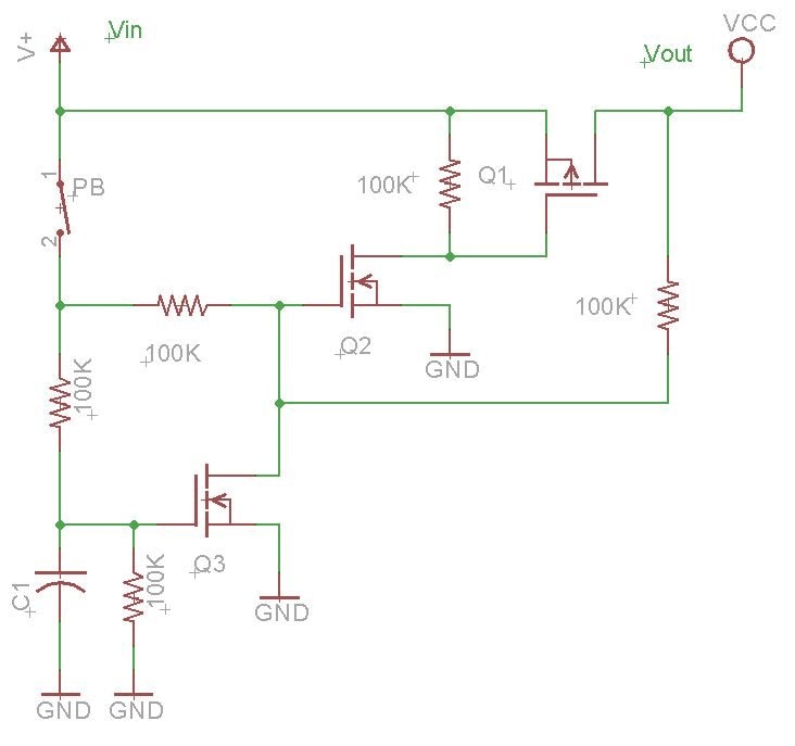
For a project I'm working on, I want to turn it on and off using only a single button, but in such a way that when you press it turns ON, but for you to turn OFF the device, you need to hold it for a longer period, let's say 5 seconds for example. I was just wondering if you have any circuit ideas that you would like to propose. I've been looking online already of course, and have found one circuit that I will be trying, it's on this link:

http://www.mosaic-industries.com/embedded-systems/microcontroller-projects/electronic-circuits/push-button-switch-turn-on/latching-toggle-power-switch

Fig6

So my list of requirements for it would be:

  • Press ON
  • Hold OFF
  • (Almost) No power draw when OFF since my idea is for it to be battery-powered
  • I would love to read the state of the button with a microcontroller, but the microcontroller can't be used for the latching part, I'm already stretching the MCU thin, and I would need to add an IO expander which I would rather not do at the moment.

Thanks for any tips that you have!

Milos

  • Sign in to reply
  • Cancel

Top Replies

  • dougw
    dougw over 1 year ago +4
    This circuit only consumes leakage current when off... You might need a diode in the gate path of Q3 and a pull down resistor on Q2.
  • misaz
    misaz over 1 year ago +4
    Look at MAX16150. It includes almost all you need in tiny SOT23-6 (or WLP) package.
  • genebren
    genebren over 1 year ago +3
    I have used a power latching circuit in a lot of my designs. But instead of adding extra circuitry, I used existing circuits with a few added components. This works given that there is a need for a microprocessor…
  • dougw
    0 dougw over 1 year ago

    This circuit only consumes leakage current when off...

    You might need a diode in the gate path of Q3 and a pull down resistor on Q2.

    image

    • Cancel
    • Vote Up +4 Vote Down
    • Sign in to reply
    • Verify Answer
    • Cancel
  • misaz
    0 misaz over 1 year ago

    Look at MAX16150. It includes almost all you need in tiny SOT23-6 (or WLP) package.

    • Cancel
    • Vote Up +4 Vote Down
    • Sign in to reply
    • Verify Answer
    • Cancel
  • genebren
    0 genebren over 1 year ago

    I have used a power latching circuit in a lot of my designs.  But instead of adding extra circuitry, I used existing circuits with a few added components. This works given that there is a need for a microprocessor and some other power circuitry.  In this case, a lot of my designs will have a Li-Ion battery and will also have an onboard battery charger, a 5V boost circuit and a microprocessor. Here is one such design (a 5V power pack).

    image

    The pushbutton (PB1) enables the 5V boost circuit (U3), which in turn powers the 3.3V regulator (U5) via Schottky diode (D3) , turning on the microprocessor (U4). The microprocessor checks the battery voltage and if sufficient, it latches on the 5V Boost circuit (through R15).  Now the circuit is on.  The microprocessor continues to monitor the pushbutton, looking for an extended press (I think I use 3-5seconds).  If the microprocessor sees an extended press, it removes the enable to the 5V Boost circuit and when the button is finally released the power turns off.  I use the LEDs to confirm that the pushbutton has been sensed in the long press by turning on all the LEDs so that the user knows that the unit will be turning off.  Also, the microprocessor monitors the battery voltage and forces a shutdown if the voltage drops to an unsafe level (over discharge is not good for Li-Ion batteries)

    Note, the when the USB power is supplied to the charger chip, the power is also routed to the 3.3V regulator to power up the microprocessor (but not the 5V Boost), so the microprocessor can monitor the charge process using the LEDs to indicate charging status (turning the LEDs on/off in sequence at a rate determined by the charging current).

    Not the simplest approach, but one that works well with battery powered devices.

    • Cancel
    • Vote Up +3 Vote Down
    • Sign in to reply
    • Verify Answer
    • Cancel
  • baldengineer
    0 baldengineer over 1 year ago in reply to misaz

    That’s a cool little chip! I looked up the price. Even in quantity, Maxim is very proud of them!

    • Cancel
    • Vote Up +2 Vote Down
    • Sign in to reply
    • Verify Answer
    • Cancel
  • genebren
    0 genebren over 1 year ago in reply to baldengineer

    Maxim is proud of a lot of their products.  They have some interesting pricing ideas.  So interesting that I do not find myself using any of their products.

    • Cancel
    • Vote Up +1 Vote Down
    • Sign in to reply
    • Verify Answer
    • Cancel
  • shabaz
    0 shabaz over 1 year ago

    A couple more ideas to add to the list!:

    I wasn't sure if by "press ON" you meant "long press" or "short press" was OK for switch-on. Long-press is worth considering sometimes, to reduce the chance of accidentally switching on portable equipment (which may then need auto-power-off). In other words, long-press-on, and long-press-off could be worth considering.

    A lot of circuits on the Internet have small idiosyncracies, such as capacitors which need time to discharge, sometimes resulting in the user being unable to turn on the circuit quickly after switching it off or turning off when the button is released rather than when the button is pressed, which may be unintuitive, and so on.

    So, idea (1) is to use logic, e.g. 74HC can be pretty low power. An example of a circuit with long-press-on and long-press-off that needs one counter IC (could be replaced with other 74HC parts too, depending on what's cheaper), and one single-gate inverter, is here:  Building an RF Switching Unit (in the section titled power on/off circuitry). That circuit allowed the complete elimination of the microcontroller (I needed low noise for that application), with the same button also detecting short-press in theory either with a microcontroller as you may want, or in that blog post, by another logic chip that allowed a selection of four settings, and a long-press would power off, and everything was reset on the long-press-on. I don't know of a negative idiosyncrasy with that circuit, it's been working since I made that board, since April 2021 on the same batteries, so it's low power.

    Such a circuit can be large, but small size isn't always necessary, and it's quite cheap.

    Since lots of functionality was given to a single button, I decided to describe it simply as "HOLD ON/OFF" and "1/2/3/4" on the silkscreen, to try to show that short-presses did functions 1-4. and long-presses did the power control. I liked that everything felt intuitive, with all operations changing on button-press, and not on button-release.

    image

    Idea (2) is to have a more general-purpose solution like Gene's, i.e. to implement power management IC (PMIC) capability in a microcontroller, because requirements can change, and logic gate circuits such as (1) cannot be quickly modified. With the microcontroller you can also do fancy stuff if it were ever needed, like auto-power-off. MSP 430 is one of several decent options, and the batteries would last years. It can also be low-cost if you need extra features that you could integrate into the same code. An example of MSP 430 power management is here:  Energy Saving: Building a Microcontroller-based System Power Controller 
    I didn't implement a push-button (because I didn't need it) but it would have been easy to do that in several ways, for instance allowing the main microcontroller to apply a KEEP_AWAKE signal (which is in that circuit) to the MSP 430 chip if a push-button applies power to the MSP 430, or alternatively modify the MSP 430 code to do the latching standalone since there are plenty of available pins on the MSP 430.

    That MSP 430 PMIC was used in this project:  Pico IoT LoRaWAN EasyNode   where the MSP 430 internal software RTC was used to periodically wake up the more power-hungry RP2040 chip, and keep it powered up for as long as necessary. The MSP430 chips can be low-cost, although prices have gone up in the past year or so. Since it can incorporate functionality like RTC and NVRAM in software, it might save costs overall if those features are needed. Plus it's easy-to-interface, by using I2C. Effectively it becomes an external peripheral for power management and additional functionality.

    • Cancel
    • Vote Up +1 Vote Down
    • Sign in to reply
    • Verify Answer
    • Cancel
  • misaz
    0 misaz over 1 year ago in reply to baldengineer

    Most of their chips are expensive. In opposition they send up to 4pcs free samples.

    • Cancel
    • Vote Up +1 Vote Down
    • Sign in to reply
    • Verify Answer
    • Cancel
  • colporteur
    0 colporteur over 1 year ago

    I'm not sure of what the signal is feeding but have you considered software control.

    I have varied the length of a button-press when feeding a Raspberry Pi's GPIO. Your discussion didn't speak to what the button is feeding. If the button is not feeding an input that is programmable then my suggestion can be thrown out with the bath water.

    • Cancel
    • Vote Up +1 Vote Down
    • Sign in to reply
    • Verify Answer
    • Cancel
  • koudelad
    0 koudelad over 1 year ago in reply to genebren

    Exactly. Why use this IC, when you can use more 8/16/32b micro-controllers for the same price? Smiley

    • Cancel
    • Vote Up +1 Vote Down
    • Sign in to reply
    • Verify Answer
    • Cancel
  • koudelad
    0 koudelad over 1 year ago

    Have you considered an 8bit micro-controller in 6 pin SOT23-6 package, like PIC10F320 or similar?

    • Cancel
    • Vote Up +2 Vote Down
    • Sign in to reply
    • Verify Answer
    • Cancel
>
element14 Community

element14 is the first online community specifically for engineers. Connect with your peers and get expert answers to your questions.

  • Members
  • Learn
  • Technologies
  • Challenges & Projects
  • Products
  • Store
  • About Us
  • Feedback & Support
  • FAQs
  • Terms of Use
  • Privacy Policy
  • Legal and Copyright Notices
  • Sitemap
  • Cookies

An Avnet Company © 2025 Premier Farnell Limited. All Rights Reserved.

Premier Farnell Ltd, registered in England and Wales (no 00876412), registered office: Farnell House, Forge Lane, Leeds LS12 2NE.

ICP 备案号 10220084.

Follow element14

  • X
  • Facebook
  • linkedin
  • YouTube