element14 Community
element14 Community
    Register Log In
  • Site
  • Search
  • Log In Register
  • Community Hub
    Community Hub
    • What's New on element14
    • Feedback and Support
    • Benefits of Membership
    • Personal Blogs
    • Members Area
    • Achievement Levels
  • Learn
    Learn
    • Ask an Expert
    • eBooks
    • element14 presents
    • Learning Center
    • Tech Spotlight
    • STEM Academy
    • Webinars, Training and Events
    • Learning Groups
  • Technologies
    Technologies
    • 3D Printing
    • FPGA
    • Industrial Automation
    • Internet of Things
    • Power & Energy
    • Sensors
    • Technology Groups
  • Challenges & Projects
    Challenges & Projects
    • Design Challenges
    • element14 presents Projects
    • Project14
    • Arduino Projects
    • Raspberry Pi Projects
    • Project Groups
  • Products
    Products
    • Arduino
    • Avnet & Tria Boards Community
    • Dev Tools
    • Manufacturers
    • Multicomp Pro
    • Product Groups
    • Raspberry Pi
    • RoadTests & Reviews
  • About Us
  • Store
    Store
    • Visit Your Store
    • Choose another store...
      • Europe
      •  Austria (German)
      •  Belgium (Dutch, French)
      •  Bulgaria (Bulgarian)
      •  Czech Republic (Czech)
      •  Denmark (Danish)
      •  Estonia (Estonian)
      •  Finland (Finnish)
      •  France (French)
      •  Germany (German)
      •  Hungary (Hungarian)
      •  Ireland
      •  Israel
      •  Italy (Italian)
      •  Latvia (Latvian)
      •  
      •  Lithuania (Lithuanian)
      •  Netherlands (Dutch)
      •  Norway (Norwegian)
      •  Poland (Polish)
      •  Portugal (Portuguese)
      •  Romania (Romanian)
      •  Russia (Russian)
      •  Slovakia (Slovak)
      •  Slovenia (Slovenian)
      •  Spain (Spanish)
      •  Sweden (Swedish)
      •  Switzerland(German, French)
      •  Turkey (Turkish)
      •  United Kingdom
      • Asia Pacific
      •  Australia
      •  China
      •  Hong Kong
      •  India
      •  Korea (Korean)
      •  Malaysia
      •  New Zealand
      •  Philippines
      •  Singapore
      •  Taiwan
      •  Thailand (Thai)
      • Americas
      •  Brazil (Portuguese)
      •  Canada
      •  Mexico (Spanish)
      •  United States
      Can't find the country/region you're looking for? Visit our export site or find a local distributor.
  • Translate
  • Profile
  • Settings
Experts, Learning and Guidance
  • Technologies
  • More
Experts, Learning and Guidance
Ask an Expert Forum cga to vga converter uPython
  • Blog
  • Forum
  • Documents
  • Leaderboard
  • Files
  • Members
  • Mentions
  • Sub-Groups
  • Tags
  • More
  • Cancel
  • New
Join Experts, Learning and Guidance to participate - click to join for free!
Actions
  • Share
  • More
  • Cancel
Forum Thread Details
  • State Not Answered
  • Replies 46 replies
  • Subscribers 290 subscribers
  • Views 5933 views
  • Users 0 members are here
  • python
  • raspberry pico
  • ask_an_expert
  • microcontrollers
  • teensy
  • vga
Related
See a helpful answer?

Be sure to click 'more' and select 'suggest as answer'!

If you're the thread creator, be sure to click 'more' then 'Verify as Answer'!

cga to vga converter uPython

rlaci
rlaci over 1 year ago

Hi

im new to uPython and needing some help with fast interrupts, port handling, reading into controller, handling the big amount of data and speed

my main aim is to get it working on raspberry pico, as colors 1bit resolution is enought as its an industrial equiment with RGBHV 15.6khz input(output from the machine) need to transfer it to 31khz VGA standard output for an lcd monitor

any help welcome

thanks!

  • Sign in to reply
  • Cancel

Top Replies

  • shabaz
    shabaz over 1 year ago +3
    There's a website listing monitors that support your resolution: http://15khz.wikidot.com/ I think it's far more likely that you'll be able to source a monitor if you search long enough on eBay, than…
  • beacon_dave
    beacon_dave over 1 year ago in reply to shabaz +3
    There is a PIO based implementation of a VGA driver discussed here if anyone is interested: https://www.youtube.com/watch?v=ZXMdZGQzrWg
  • michaelkellett
    michaelkellett over 1 year ago in reply to rlaci +3
    It's very, very difficult. You need to delve quite deeply into the data sheets. The things to look for are the IO toggle rate, maximum clock rate of internal RAM, and maybe some benchmarks of complete…
Parents
  • shabaz
    0 shabaz over 1 year ago

    There's a website listing monitors that support your resolution: http://15khz.wikidot.com/

    I think it's far more likely that you'll be able to source a monitor if you search long enough on eBay, than to convert the sync rate with a Pico.

    If you were to use a Pico, you'd need to figure out how to convert the analog signal in to digital for the Pico to read in, and then figure out out how to send out an analog signal (that latter part is slightly easier, it's been done before I expect). But none of that will work with native microPython (if I assume you've already searched for a library for it, and not found it), and will likely require assembler coding (for the internal units known as PIO). It's a steep learning curve if you need help with everything you've listed above. 

    There may be other ready-made converters out there.

    • Cancel
    • Vote Up +3 Vote Down
    • Sign in to reply
    • Verify Answer
    • Cancel
  • rlaci
    0 rlaci over 1 year ago in reply to shabaz

    - its an industrial equipment so no analog signal needed just low or high

    -  one color as it only shows text is acceptable

    - its showing text i think the 320x200(my predicted resolution) could be shrinked down to like 120x80 or something

    - as of my own im thinking about leaving the Vsync and leaving the Hsync also, but one interrupt driven pico input could make in half period a second trigger so in this way the Hsync is doubled. with signal generator i was able to sync up the vga monitor, but the left part of the original screen is also written on the original right part of the screen so its messy but at least i can see the source equipment is working, but line doubling like that isnt really a solution i need to part it so if i could make a fast enought program to read one line and write two with the information from the one but double freq/half period

    - my second idea is to read a whole image then visualise with a resolution as i want as driving a vga display is not that hard, but im not sure what kind of variable library could hold up the whole image data as im new to python, i dont even know which way is proper for one line bit transforming

    one color possibly reduced resolution is my first goal

    - im also thinking about making a trigger driving a flipflop at half sync period then drive 2 monitors with half part of the original signal but its a pretty messy solution

    • Cancel
    • Vote Up 0 Vote Down
    • Sign in to reply
    • Verify Answer
    • Cancel
  • shabaz
    0 shabaz over 1 year ago in reply to rlaci

    If it's just 1-bit data (i.e. R/G/B are all the same, and only two values) then that's a lot easier.

    However, I'm not sure why you think microPython will work here. It's too slow for this. If you wish to do it with a Pico, then you'd ideally need to read up on the Pico's PIO (Programmable Input/Output) feature, and learn how to use that. With that, it could be fairly straightforward to do what you want, perhaps translating each raster line to two, for CGA->VGA, or writing to frame buffers, you have the memory for that option too. You'll be in a better position to decide that once you've use the PIO capabilities a bit. Note that there are two PIOs, so you can use both if it simplifies things. I suspect you may need to use two since each one can only have a limited amount of instructions.

    So, the language to read up on and experiment with is PIO assembler, plus a bit of C (other languages are possible, but C would be easiest) for any setup code as required. You could even drive a LCD screen. If you're completely new to all this, all I can suggest is do some simpler experiments first, and get used to using an oscilloscope to help monitor and debug your PIO code.

    As mentioned before, picking up an off-the-shelf 15kHz compatible monitor would be the simplest option though.

    • Cancel
    • Vote Up +1 Vote Down
    • Sign in to reply
    • Verify Answer
    • Cancel
Reply
  • shabaz
    0 shabaz over 1 year ago in reply to rlaci

    If it's just 1-bit data (i.e. R/G/B are all the same, and only two values) then that's a lot easier.

    However, I'm not sure why you think microPython will work here. It's too slow for this. If you wish to do it with a Pico, then you'd ideally need to read up on the Pico's PIO (Programmable Input/Output) feature, and learn how to use that. With that, it could be fairly straightforward to do what you want, perhaps translating each raster line to two, for CGA->VGA, or writing to frame buffers, you have the memory for that option too. You'll be in a better position to decide that once you've use the PIO capabilities a bit. Note that there are two PIOs, so you can use both if it simplifies things. I suspect you may need to use two since each one can only have a limited amount of instructions.

    So, the language to read up on and experiment with is PIO assembler, plus a bit of C (other languages are possible, but C would be easiest) for any setup code as required. You could even drive a LCD screen. If you're completely new to all this, all I can suggest is do some simpler experiments first, and get used to using an oscilloscope to help monitor and debug your PIO code.

    As mentioned before, picking up an off-the-shelf 15kHz compatible monitor would be the simplest option though.

    • Cancel
    • Vote Up +1 Vote Down
    • Sign in to reply
    • Verify Answer
    • Cancel
Children
  • rlaci
    0 rlaci over 1 year ago in reply to shabaz

    15khz monitor i picked up is not working with this signal, but i was able to visualize with synthetic clock on the HV pins

    - with teensy 3.2 in arduino only 12Mhz and the signal wasnt too symetric. i bet arduino compiller ads some instructions to the code even when you are using asm code

    - with micropython i was able to reach 62MHz freq with PICO and I have a teensy 4.1on my desk if pico isnt enought but i believe it is

    as far as my equipment i have a fluke 124 scopemeter and digital discovery 3 as logic analyzator, generator etc

    do you have experience with upython programming? advice for learning stuff connected with porting and asm code for different controllers? i think im gonna stuck with teensy and pico in the future

    • Cancel
    • Vote Up 0 Vote Down
    • Sign in to reply
    • Verify Answer
    • Cancel
  • shabaz
    0 shabaz over 1 year ago in reply to rlaci

    Regarding:

    with micropython i was able to reach 62MHz freq with PICO 

    Could you share the code you used to achieve that?

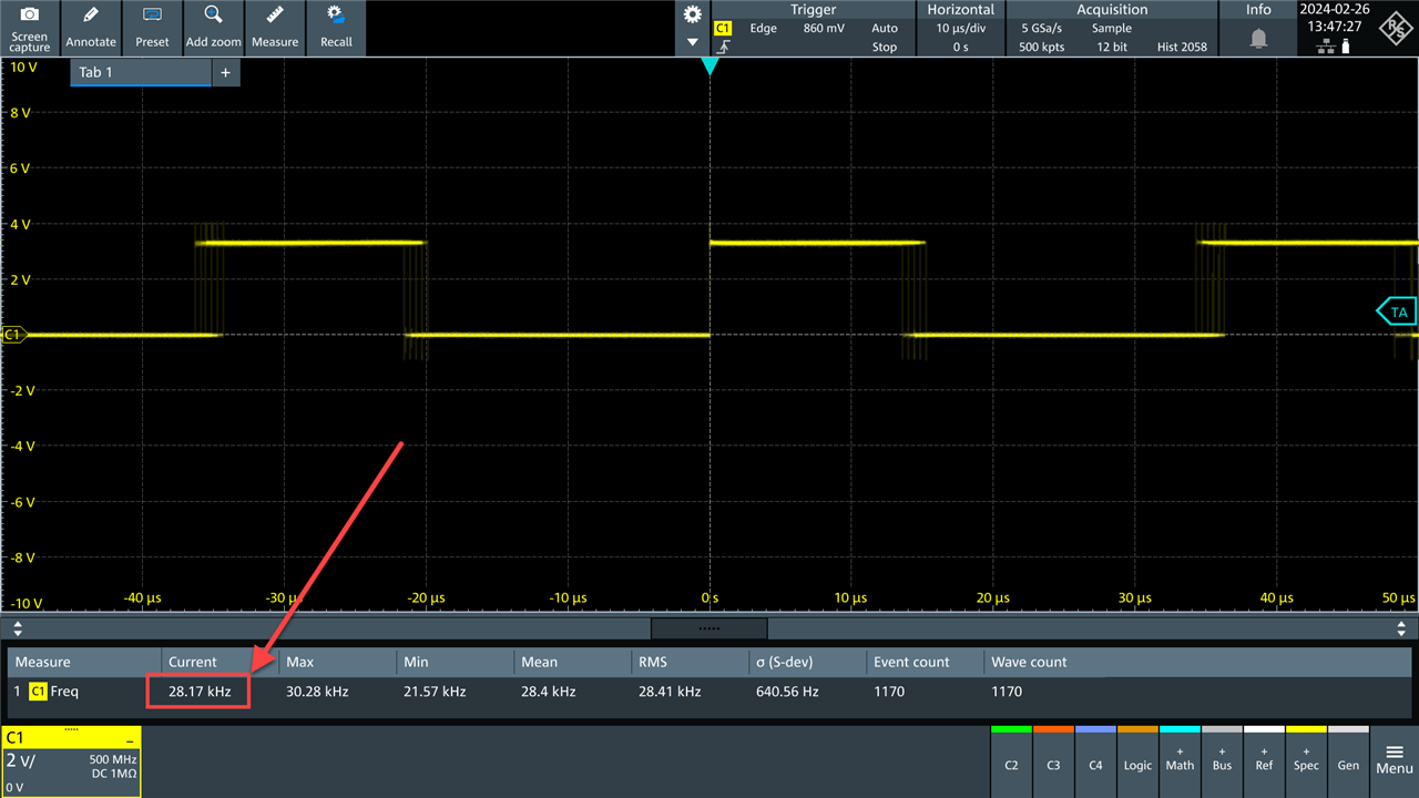
    I see vastly different results with a simple speed test; 28 kHz, and with significant jitter. That's a world apart from 62 MHz, so it would be good to see what you meant by that.

    image

    For reference, here is the code I used:

    import time
    from machine import Pin
    
    
    # GPIO
    in_pin = Pin(16, Pin.IN, Pin.PULL_UP)
    out_pin = Pin(15, Pin.OUT)
    
    # main function
    def app_main():
    
        print("starting..")
    
        for i in range(0, 1e5):
            v = in_pin.value()
            out_pin.value(1)
            v = in_pin.value()
            out_pin.value(0)
        print("done.")
    

    Note: if you achieved 62 MHz by using SPI, that's actually using the PIO (or a hardware peripheral inside the microcontroller in question). All I can conclude from my test, shown above, is that micropython on it's own won't achieve anywhere near the speeds you're mentioning; it will require PIO coding.

    • Cancel
    • Vote Up +2 Vote Down
    • Sign in to reply
    • Verify Answer
    • Cancel
  • beacon_dave
    0 beacon_dave over 1 year ago in reply to shabaz

    There is a PIO based implementation of a VGA driver discussed here if anyone is interested:

    https://www.youtube.com/watch?v=ZXMdZGQzrWg

    • Cancel
    • Vote Up +3 Vote Down
    • Sign in to reply
    • Verify Answer
    • Cancel
  • rlaci
    0 rlaci over 1 year ago in reply to shabaz

    throught PIO and it was stable, the regular programmed solution is comparable with arduino uno with original library. pico is running at 125mhz and that 62 was exactly the half of it.

    now and even before i had a problem with interrupts, i thought they are instant but not at all it takes up some useconds to act as i have measured in some tests. do you have some info about which board has what kind of latency for interrupts?

    xvga adapter was ordered already it should work but as a curiosity i would be interested to play a little more with this problem

    bitluni has some fast libraries for esp32 but still hesitating if some interrupted input, or what kind of input could read the original displays pixels well. possibly it would take 2 microcontrollers or a 2core system like the pico. one reading the other one writing the output.

    the hsync and vsync by warming up the cnc machine changes a little bit so synchronizing to that signal i think is out of question especially as interrupt isnt that fast as i thought

    • Cancel
    • Vote Up 0 Vote Down
    • Sign in to reply
    • Verify Answer
    • Cancel
  • shabaz
    0 shabaz over 1 year ago in reply to rlaci

    I didn't understand most of that I'm afraid. Interrupts are still not going to help with MicroPython, regardless of ESP32 or Pico. And the comment about 62 MHz being half of 125 MHz is irrelevant when using MicroPython.

    You don't need to use interrupts if you use the PIO (at least, not for the content per raster line, maybe you might want to use interrupts for some other purpose, but you probably need to sketch out what you would implement in code in the PIO and what would be elsewhere (e.g. in C).

    To me, it seems straightforward at a high level; read in data samples asynchronously, triggered on the sync signal (possibly without interrupt, just using PIO,but it's up to your design of it all), and then when you've got one raster of data (or when you've got one picture frame of data - depending on how much memory there it, I've not done the sum), you'd output two lines, or drop every other sample, to increase the output raster line speed.

    You still have not really decided on a path forward though, if you're contemplating ESP32 (ESP32 doesn't have PIO), and at some point you need to decide to prototype up a few things, to answer a few unknowns, to see which processor, and which method is worth investing more time into, and just accept that some of the initial prototyping might get thrown out of the window if/when you need to switch approach. 

    • Cancel
    • Vote Up 0 Vote Down
    • Sign in to reply
    • Verify Answer
    • Cancel
  • rlaci
    0 rlaci over 1 year ago in reply to shabaz

    what you concluded i already worked out in my mind and the implications:

    - async read of 400bits with only one sync signal not gonna work

    - synced read of pixels at around 6MHz could work, but i still have to sync up the picture to not be shifted, reading 2 lines then writing one gonna be shifted over because of the shifting frequency of the original equipment and storing only one line of data do not really gives place to start the display from the beginning and messing up the sygnal with the orignal one could desynchronize the vga output. my first approach was to only double the HSYNC to at lest see if the cnc is sending out data or not

    as i dived into it firstly looks like easy math, but because of the speed of signals and timing its a pretty hard task to accomplish, but i still think its doable and yes im not fully decided if i could find a code halfway working already im going with that board. with a perfect code possibly even an arduino uno could drive it on the edge, but esp and pico are both capable boards both i just have to learn them better

    • Cancel
    • Vote Up 0 Vote Down
    • Sign in to reply
    • Verify Answer
    • Cancel
  • shabaz
    0 shabaz over 1 year ago in reply to rlaci

    Hi,

    Async read of an entire line could certainly work, with the async line capture initially triggered from the sync  signal. Anyway, it's likely time to spend a week or two trying out some hardware (it doesn't cost a lot), to investigate what limits you will hit, and what you're comfortable coding with, to rule things in or out, because it seems that's a significant grey area currently, because expectations (Python, Arduino etc) are not aligned with what may be feasible (I feel) but it also depends on what you will be OK coding for.

    • Cancel
    • Vote Up 0 Vote Down
    • Sign in to reply
    • Verify Answer
    • Cancel
  • rlaci
    0 rlaci over 1 year ago in reply to shabaz

    if you tell me how can i read asynchronously one line with the bit positions without any clock signal then reproduce it at the exact positions i would be very happy because i think its nonsense

    as i experienced this VGA thing is pretty broadely understuud and sometimes there is a pixelclock for blank signals too sometimes nothing (actually measured it) and the VGA decoder chip sometimes reads a whole different resolution by its own as you are sending to and it all depends on the monitor side

    i feel you do not like python but i think to use python for pio setup what part is assembler language and the same for c sdk im not sure what the problem is there especially if im using the DMA

    yes it looks like a trivial task, but at high speeds some problems start to occur but you are right im a pretty beginner in microchip programming, im looking up the pico deeply now and would like to use that board as now i know it can do it for sure. i was switching between boards in the beginning, because i was not sure, please wish me luck or try to send some code to help if you want just stay positive please

    • Cancel
    • Vote Up 0 Vote Down
    • Sign in to reply
    • Verify Answer
    • Cancel
  • shabaz
    0 shabaz over 1 year ago in reply to rlaci

    If you're sure you wish to proceed with Pico, then it will require assembler programming for the Pico's internal PIO module(s).
    The PIO is described in a user manual on the Raspberry Pi website (there are useful videos too, but everyone's primary source of info is the user manual), and there's lots of example code on the official GitHub site, but for sure there won't be a CGA to VGA converter, that's too niche. But there is very likely to be VGA output example code on the Internet for the Pico, so that you have something to examine.

    To learn to use the PIO, that's best achieved by reading the manual (it is well-written and there are only half a dozen or so instructions to learn, although there's approx. half a dozen concepts that can be applied to each instruction type), and try to follow some example code to make sense of it, and then try to read in data, and try to write out data, and learn how to use DMA, and stick with C to interface your code. It's difficult enough to learn something new, than to try to layer on another programming language when the bulk of the examples will combine the PIO with C, not Python. If C is new, then that's not an overly difficult language either, and you might not need to learn a lot, if you get lucky and find examples close to the task you're doing. For instance, if you wish to "do something" once a line, or once a frame of data has been received, then look for examples which use DMA to transfer data from the PIO for _any_ purpose, and the PIO code, and C code there will be approximately what you need for that specific bit of functionality.

    It's difficult to predict, but I think as a beginner, you may need to spend a week or so learning about PIO, trying some examples. If you're new to C, that requires a couple of weeks study and practice (I can recommend some books if you need that). Then expect to spend a further 3 weeks or so to experiment a bit, and design, develop and test your code (ballpark), and you may well have to scrap things and try different approaches, if you hit limits (because there are some limits with PIO), so it's best to experiment a bit first with some simpler projects, and examine with a 'scope, or other forms of debug, what's going on.

    EDIT: Just realized beacon_dave has already shared an example of PIO for VGA output, so you've got something to begin learning.

    • Cancel
    • Vote Up 0 Vote Down
    • Sign in to reply
    • Verify Answer
    • Cancel
element14 Community

element14 is the first online community specifically for engineers. Connect with your peers and get expert answers to your questions.

  • Members
  • Learn
  • Technologies
  • Challenges & Projects
  • Products
  • Store
  • About Us
  • Feedback & Support
  • FAQs
  • Terms of Use
  • Privacy Policy
  • Legal and Copyright Notices
  • Sitemap
  • Cookies

An Avnet Company © 2025 Premier Farnell Limited. All Rights Reserved.

Premier Farnell Ltd, registered in England and Wales (no 00876412), registered office: Farnell House, Forge Lane, Leeds LS12 2NE.

ICP 备案号 10220084.

Follow element14

  • X
  • Facebook
  • linkedin
  • YouTube