Hello,
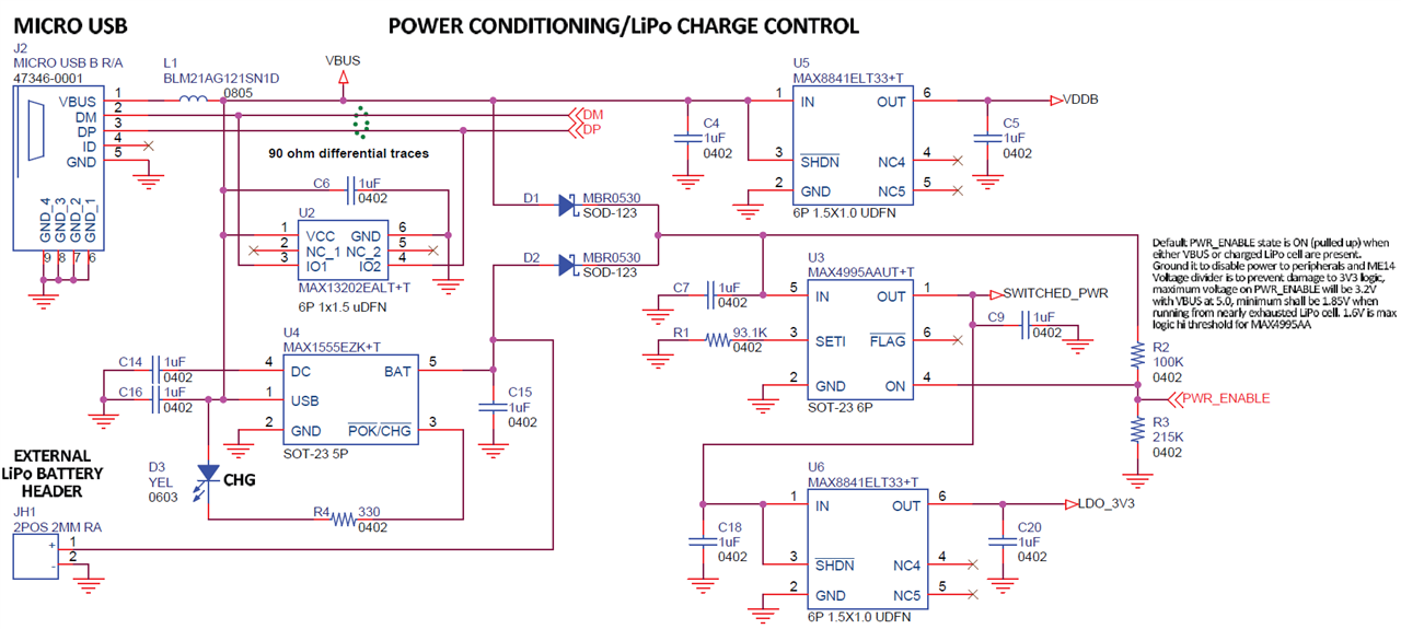
I have a MAX32666FTHR board that embeds a MAX1555 IC to handle charging a LiPo battery, as seen on this diagram:
In the circuit I'm building around that board, I'm using a display made of 64 WS2812B LEDs that is powered with +5V and consumes around 1A when fully lit.
To generate that +5V from the battery, I can use a boost DC DC converter quite easily, I just need to take into account the fact that it consumes a lot of current, and so the battery cannot be small if I want it to work for more than a few minutes. As such, I'm looking at 5000 to 10000mAh batteries.
Thing is, the MAX1555 used here is only consuming 100mA at most while charging, meaning that it would take anywhere between 2 to 4 days to fully charge the selected battery.
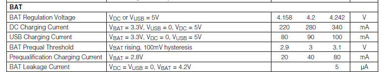
So, to speed up things quite a bit, I'm considering this kind of module:
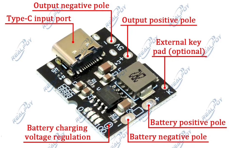
It's specifications tell me that it can charge a 2A, thus getting around 2.5 to 5 hours charge time. And it is also capable of outputting 5V at 2A, way more than what I need in my project.
So far so good, but I'm wondering how to connect all this together, preserving functionality as much as possible, with as little user manipulation as possible.
At first, I thought about desoldering the VBUS pin on J2 and connecting VBUS to the module output. But this makes the VDDB signal always present which tricks the MAX32666 into thinking it is connected to a USB host when it is not actually so. And I'd really like to be able to continue using the available USB stack implementation in my project.
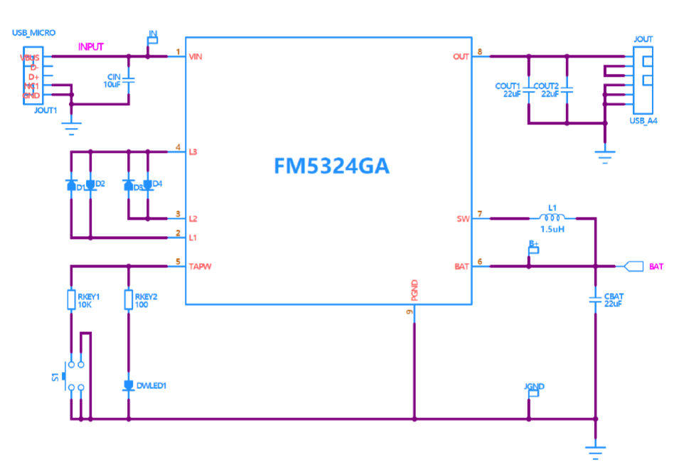
My other idea is to connect the battery to both the module and the max32666FTHR board battery header, like this:
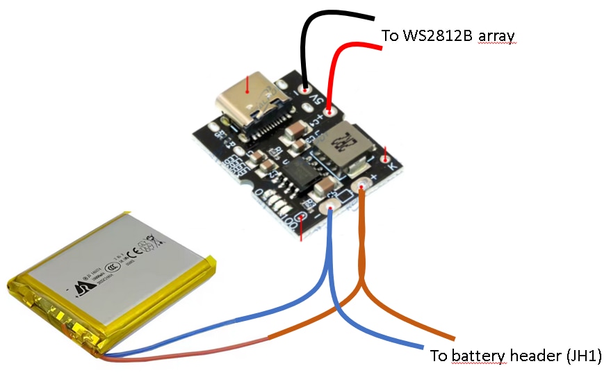
The battery has its own integrated protection circuit.
However, I have two concerns with this:
The first is about the survival of the MAX1555 when the battery is under charge by the module. I think it would not mind as it would see 4.2V on its BAT pin, way below the maximum value (7V in the datasheet).
The second is about the survival of the charging chip inside the module when I plug a micro USB cable in J2 on the board. This would put the MAX1555 into charging mode, thus sending 4V into the positive cable of the battery and into the module charging chip, but I believe this should be fine as would be the case in the reverse situation.
What do you think of this? Am I right in assuming the second idea is fine for both charger ICs?
Thanks for your help