element14 Community
element14 Community
    Register Log In
  • Site
  • Search
  • Log In Register
  • Community Hub
    Community Hub
    • What's New on element14
    • Feedback and Support
    • Benefits of Membership
    • Personal Blogs
    • Members Area
    • Achievement Levels
  • Learn
    Learn
    • Ask an Expert
    • eBooks
    • element14 presents
    • Learning Center
    • Tech Spotlight
    • STEM Academy
    • Webinars, Training and Events
    • Learning Groups
  • Technologies
    Technologies
    • 3D Printing
    • FPGA
    • Industrial Automation
    • Internet of Things
    • Power & Energy
    • Sensors
    • Technology Groups
  • Challenges & Projects
    Challenges & Projects
    • Design Challenges
    • element14 presents Projects
    • Project14
    • Arduino Projects
    • Raspberry Pi Projects
    • Project Groups
  • Products
    Products
    • Arduino
    • Avnet & Tria Boards Community
    • Dev Tools
    • Manufacturers
    • Multicomp Pro
    • Product Groups
    • Raspberry Pi
    • RoadTests & Reviews
  • About Us
  • Store
    Store
    • Visit Your Store
    • Choose another store...
      • Europe
      •  Austria (German)
      •  Belgium (Dutch, French)
      •  Bulgaria (Bulgarian)
      •  Czech Republic (Czech)
      •  Denmark (Danish)
      •  Estonia (Estonian)
      •  Finland (Finnish)
      •  France (French)
      •  Germany (German)
      •  Hungary (Hungarian)
      •  Ireland
      •  Israel
      •  Italy (Italian)
      •  Latvia (Latvian)
      •  
      •  Lithuania (Lithuanian)
      •  Netherlands (Dutch)
      •  Norway (Norwegian)
      •  Poland (Polish)
      •  Portugal (Portuguese)
      •  Romania (Romanian)
      •  Russia (Russian)
      •  Slovakia (Slovak)
      •  Slovenia (Slovenian)
      •  Spain (Spanish)
      •  Sweden (Swedish)
      •  Switzerland(German, French)
      •  Turkey (Turkish)
      •  United Kingdom
      • Asia Pacific
      •  Australia
      •  China
      •  Hong Kong
      •  India
      • Japan
      •  Korea (Korean)
      •  Malaysia
      •  New Zealand
      •  Philippines
      •  Singapore
      •  Taiwan
      •  Thailand (Thai)
      • Vietnam
      • Americas
      •  Brazil (Portuguese)
      •  Canada
      •  Mexico (Spanish)
      •  United States
      Can't find the country/region you're looking for? Visit our export site or find a local distributor.
  • Translate
  • Profile
  • Settings
Experts, Learning and Guidance
  • Technologies
  • More
Experts, Learning and Guidance
Ask an Expert Forum Looking for an LED driver recommendation
  • Blog
  • Forum
  • Documents
  • Leaderboard
  • Files
  • Members
  • Mentions
  • Sub-Groups
  • Tags
  • More
  • Cancel
  • New
Join Experts, Learning and Guidance to participate - click to join for free!
Actions
  • Share
  • More
  • Cancel
Forum Thread Details
  • State Not Answered
  • Replies 15 replies
  • Subscribers 308 subscribers
  • Views 245 views
  • Users 0 members are here
  • prototype
  • drivers
  • led_driver
Related
See a helpful answer?

Be sure to click 'more' and select 'suggest as answer'!

If you're the thread creator, be sure to click 'more' then 'Verify as Answer'!

Looking for an LED driver recommendation

colporteur
colporteur 3 days ago

image

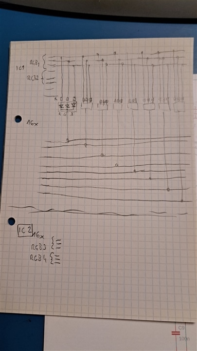
I'm looking for some suggestions on a replacement LED driver circuit for the one above..

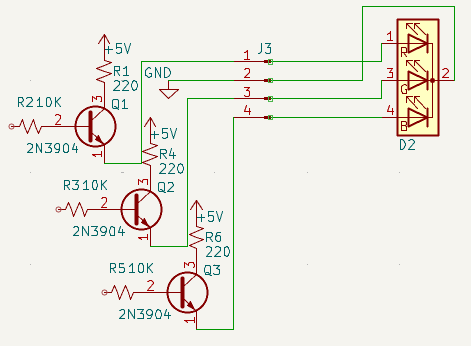
I have 10 common cathode tri-colour LEDs I need to drive. I banged out this transistor circuit to isolate the LED's from the Arduino. A HIGH output from the Arduino should light the LED. I've used the transistor circuit on a small scale for driving LEDs. My formal training was in electronics but 20 years ago my career forked to computer networks as a system administrator and the electronics became a thing for hobbies.

I then thought there has to be an easier way. I started newark searching for possible drivers but my lack of practical experience in this area makes it tough. I'm looking for something simple that takes the load of the microcontroller. I found this SN74HCT245N bus driver and thought that might work. Four twenty pin IC's would give me 32 drivers. I need 30 in total. Simple IC's verses all the individual components would make PCB assembly definitely easier.

This is not high speed switching. It is simple on and off control for LED's. I'm hoping the folks that hang out here and do this sort of stuff all the time would have a recommendation for there go to circuits for this sort of thing. 

  • Sign in to reply
  • Cancel

Top Replies

  • colporteur
    colporteur 2 days ago in reply to beacon_dave +1
    Thank BD. It seemed strange such a popular chip for stepper motors was discontinued.
Parents
  • geralds
    0 geralds 2 days ago

    Hi https://community.element14.com/members/colporteur,

    If I've understand you, your Arduino sends a HIGH from its output-pins.

    Are the RGB-LEDs common cathodes, then you will need consider three points.
    1) you need a logical inverter
    2) you need a high side driver with PNP transistors, with that you can drive the common cathode LEDs.
    3) power dissipation. What kind, type are your RGB-LEDs? High- or Low current?

    possible Solution: - if you drive just direct the LEDs -
    1) simple inverters connected on the Arduino
    2) your high-side drivers needs e.g. BC557 or similar, or for more current BC327, or similar
    -> with this, you can drive with high current

    A ULN2xxx does not work because they are low side drivers (darlington NPN outputs)
    A 74 xx245 does not work because this is a tri-state bus driver.

    If you drive the LEDs storing the logical states, then a MAX7219 (SPI bus with Load-pin) or a MAX7221 (SPI-bus with /CS-pin) will work,
    but it has a serial input and a driver matrix output. Both drives have a DI-pin and DO-pin, so you can use it daisy-channed.
    Here you need more program code, but you can save pins on the Arduino.

    Consider the power dissipation!
    If you cannot reach, you will need external high current drivers; see point 3. Please read the datasheet (a sample schematic is shown).

    MAX7219/7221 datasheet:

    A possible way can also be using the serial-parallel decoder 74HC595.

    With this decoder - driver you can make your schematic very simple.

    As well here - Power dissipation, this driver can drive just low-current LEDs.

    Well, .... :) ... the PCB grows more complex.

    Best regards
    Gerald

    • Cancel
    • Vote Up 0 Vote Down
    • Sign in to reply
    • Verify Answer
    • Cancel
  • colporteur
    0 colporteur 1 day ago in reply to geralds

    My criteria is minimum components. UDN2981A is a source driver so it should be able to control the LEDs' with only resistor.

    I looked at the two IC above and found a SN74HCT244N driver. With a resistor for each LED I am in business I think.

    • Cancel
    • Vote Up 0 Vote Down
    • Sign in to reply
    • Verify Answer
    • Cancel
Reply
  • colporteur
    0 colporteur 1 day ago in reply to geralds

    My criteria is minimum components. UDN2981A is a source driver so it should be able to control the LEDs' with only resistor.

    I looked at the two IC above and found a SN74HCT244N driver. With a resistor for each LED I am in business I think.

    • Cancel
    • Vote Up 0 Vote Down
    • Sign in to reply
    • Verify Answer
    • Cancel
Children
  • geralds
    0 geralds 1 day ago in reply to colporteur

    Yes, I thought this too. 

    How many pins have your Arduino (which type of Arduino?) for the LEDs? I think you have not 30 pins for the LEDs (10 RGB LEDs).

    How much current does they need?

    >> If the RGB LEDs are low-current LEDs (<5mA) then you can drive this with 4 ICs 74HC595, connected in daisy-chain.

    The source code is a 30-step, serial to parallel decoding. On the Arduino you need only few pins.

    If you have higher current LEDs >>> The driver between the 74HC595 and the LEDs are the MIC2981 (this is the Microchip version, because the UDN (Allegro) is obsolete). So, you have then 8 ICs.

    -> One point: may be the SRCLK needs a delay between the 595's because H'7 and the SRCLK can have a problem synchronizing from the first to the next step.

    https://www.ti.com/lit/an/scea117/scea117.pdf

    (please read page 10 and 11 in this application report)

    May be 1 buffer IC would be adding to the schematic.

    This is what I thought for your schematics.

    • Cancel
    • Vote Up 0 Vote Down
    • Sign in to reply
    • Verify Answer
    • Cancel
element14 Community

element14 is the first online community specifically for engineers. Connect with your peers and get expert answers to your questions.

  • Members
  • Learn
  • Technologies
  • Challenges & Projects
  • Products
  • Store
  • About Us
  • Feedback & Support
  • FAQs
  • Terms of Use
  • Privacy Policy
  • Legal and Copyright Notices
  • Sitemap
  • Cookies

An Avnet Company © 2026 Premier Farnell Limited. All Rights Reserved.

Premier Farnell Ltd, registered in England and Wales (no 00876412), registered office: Farnell House, Forge Lane, Leeds LS12 2NE.

ICP 备案号 10220084.

Follow element14

  • X
  • Facebook
  • linkedin
  • YouTube