


I did a bit of a hack today : )
I have a Pi Pico, attached to an RS-485 transceiver. As you're maybe aware, the RS-485 transceiver converts the UART signal into two signals, called A and B, or Non-Inverting and Inverting. The oscilloscope trace below explains this.

What's not shown is that the A and B outputs are often only enabled if requested to do so by applying a logic high on a Driver Enable (DE) pin. If the DE pin is low, then the A and B signals will no longer output a signal.
I had a request from a friend to control an LED and a little audio tone beeper from the Pi Pico. Sometimes he wanted just the LED to light, sometimes just the beeper, and sometimes both. He doesn't need RS-485.
I initially considered opening up the device and wiring things up to spare GPIO pins internally. However, after thinking some more, I realized I could just repurpose the RS-485 connections, as shown in the video:
To get this to work, all I needed to do was a software mod, to change the Pi Pico UART Tx pin to become a normal GPIO configured as an output. Then, the logic was simple:
|
Driver Enable (DE) |
UART TXD |
RS-485 A,B |
| 1 | 0 | Low, High |
| 1 | 1 | High, Low |
| 0 | 0 | HiZ, HiZ |
| 0 | 1 | HiZ, HiZ |
I wired the little beeper to the A connection, and the LED to the B connection (use series diodes and resistors as required to reduce the voltage or current if needed), with the other end of each connected to 0V (ground).
I cannot turn on both the LED and the beeper simultaneously, but that's not a big deal, the code can just alternate every second as shown in the video.
I'll encase this in moldable plastic (PolyDoh), that will be good enough for the particular use-case.
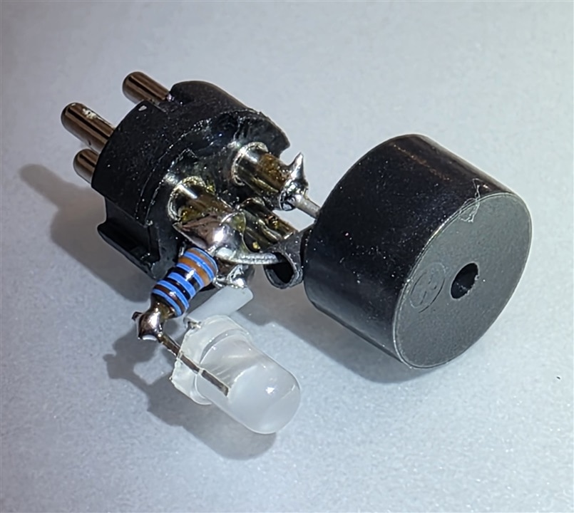
Not a very clever hack, but it did save me some effort!
Thanks for reading.


