element14 Community
element14 Community
    Register Log In
  • Site
  • Search
  • Log In Register
  • Community Hub
    Community Hub
    • What's New on element14
    • Feedback and Support
    • Benefits of Membership
    • Personal Blogs
    • Members Area
    • Achievement Levels
  • Learn
    Learn
    • Ask an Expert
    • eBooks
    • element14 presents
    • Learning Center
    • Tech Spotlight
    • STEM Academy
    • Webinars, Training and Events
    • Learning Groups
  • Technologies
    Technologies
    • 3D Printing
    • FPGA
    • Industrial Automation
    • Internet of Things
    • Power & Energy
    • Sensors
    • Technology Groups
  • Challenges & Projects
    Challenges & Projects
    • Design Challenges
    • element14 presents Projects
    • Project14
    • Arduino Projects
    • Raspberry Pi Projects
    • Project Groups
  • Products
    Products
    • Arduino
    • Avnet Boards Community
    • Dev Tools
    • Manufacturers
    • Multicomp Pro
    • Product Groups
    • Raspberry Pi
    • RoadTests & Reviews
  • Store
    Store
    • Visit Your Store
    • Choose another store...
      • Europe
      •  Austria (German)
      •  Belgium (Dutch, French)
      •  Bulgaria (Bulgarian)
      •  Czech Republic (Czech)
      •  Denmark (Danish)
      •  Estonia (Estonian)
      •  Finland (Finnish)
      •  France (French)
      •  Germany (German)
      •  Hungary (Hungarian)
      •  Ireland
      •  Israel
      •  Italy (Italian)
      •  Latvia (Latvian)
      •  
      •  Lithuania (Lithuanian)
      •  Netherlands (Dutch)
      •  Norway (Norwegian)
      •  Poland (Polish)
      •  Portugal (Portuguese)
      •  Romania (Romanian)
      •  Russia (Russian)
      •  Slovakia (Slovak)
      •  Slovenia (Slovenian)
      •  Spain (Spanish)
      •  Sweden (Swedish)
      •  Switzerland(German, French)
      •  Turkey (Turkish)
      •  United Kingdom
      • Asia Pacific
      •  Australia
      •  China
      •  Hong Kong
      •  India
      •  Korea (Korean)
      •  Malaysia
      •  New Zealand
      •  Philippines
      •  Singapore
      •  Taiwan
      •  Thailand (Thai)
      • Americas
      •  Brazil (Portuguese)
      •  Canada
      •  Mexico (Spanish)
      •  United States
      Can't find the country/region you're looking for? Visit our export site or find a local distributor.
  • Translate
  • Profile
  • Settings
Internet of Things
  • Technologies
  • More
Internet of Things
Blog Antennas for the Internet of Things
  • Blog
  • Forum
  • Documents
  • Quiz
  • Events
  • Polls
  • Members
  • Mentions
  • Sub-Groups
  • Tags
  • More
  • Cancel
  • New
Join Internet of Things to participate - click to join for free!
  • Share
  • More
  • Cancel
Group Actions
  • Group RSS
  • More
  • Cancel
Engagement
  • Author Author: gervasi
  • Date Created: 15 Jul 2016 4:08 AM Date Created
  • Views 1012 views
  • Likes 5 likes
  • Comments 4 comments
  • impedence
  • internet of things
  • antennae
  • impedance_matching
  • impedance matching
  • iot
  • field strength
  • antenna
Related
Recommended

Antennas for the Internet of Things

gervasi
gervasi
15 Jul 2016

For extreme applications, it's obvious why we need the best antenna possible.  image


For Internet of Things (IoT) applications, antenna performance may seem unimportant.  The whole idea of IoT is based on having many devices close together with inexpensive transceivers.  Despite the close range and low cost, though, antenna performance still matters.  Scroll down to Example for a real-world example of a manufacturer focused on improving antenna performance of an IoT product.

image


Why does antenna performance matter?


Noise

An IoT-enabled device may be used in noisy environments where more power is needed to overcome interfering signals on the receiver's antenna.  Regardless of the receiver's sensitivity, if it's receiving -80dBm of noise power, either from unintentional emissions from equipment or from any of the non-Bluetooth devices that share the ISM bands, it will need roughly -60dBm of signal to overcome the interference.  How much power is needed to overcome interference depends on the nature of the interference and the type of signaling the IoT system uses. 


Fading

In an indoor environment, radio waves bounce off walls and objects.  The reflections combine constructively or destructively, depending on their phase.  If you spend a long time using a wireless device indoors, you can eventually find unlucky locations where the multipath interference is particularly destructive and the signal drops 30dB.  A better antenna won't affect the depth of these “fades”, but it will raise the signal strength so that the fades don't cause the signal strength to fall below the receiver's sensitivity.


Efficiency

Every dB of increased antenna performance is potentially 1 dB less output power needed, decreasing the IoT device’s power budget. If improving the antenna decreases the number of packet retries, it can significantly improve battery life. 


Calculating Range

The signal strength at the receiver is equal to the transmitter power plus the antenna gains minus the path loss.  There is a straightforward formula for calculating path loss.  If you run the formula for the 2.4GHz ISM band at a distance of 10 meters, you find a path cost of 60dB.  A typical low-power transmitter's output is 1mW [0dBm].  A typical IoT receiver requires at least -85dBm of signal to work reliably.  In this scenario if the antennas have zero gain and there are no obstructions between them, the signal strength at the receiver will be -60dBm, 25dB more than needed.  This “extra” signal strength is called link margin. We need this link margin to handle fades, interference, detuning of the antenna due to proximity of the human body, and objects that block that path.  If the antennas have 3dB loss on both sides, the receiver only gets -66dBm of signal.  -66dBm > -85dBm, so the system will work, but the lower link margin means it will be less robust against fades and interference. 


-6dB equates to one fourth the power.  That means in the above scenario with -6dB of antenna loss, they could use one fourth the output power and get the same performance.


Example

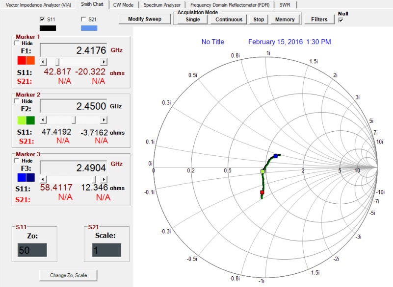
Here is an example of an IoT wall switch from Amatis Controls that uses a chip antenna.  We solder a small connector onto the board and measure the impedance of the antenna on the vector network analyzer (VNA).  On a Smith Chart view, the center of the plot represents a perfect 50 ohm match. With the default match network from the datasheet, the antenna is not well matched in the 2.4 GHz band.image

image


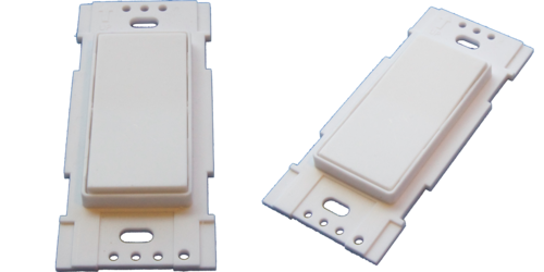
The Smith chart view lends itself, after some experience using it, to seeing which matching network values will move the impedance of the antenna closer to matched.   For more details on the matching procedure, see this post on matching an on-board antenna.


After several iterations of matching, the antenna is matched more closely to 50 ohms.

image


It’s a good idea to do field strength measurement before and after matching to see how well the received signal strength from the matched antenna agrees with strength predicted by the path loss equation.   Usually better matching means more radiated power, and radiated power will equal nearly the transmitter's output minus the reflected power observed on the VNA.  This is not always true.  In an extreme case, we could put a 50 ohm resistor (called a “dummy load” in the amateur radio world) that would dissipate the power as heat and hardly radiate at all.   We could have a very bad antenna that we manage to match to 50 ohms.  There is a saying that says “you can match to a rock, but it does not mean it's a good antenna.”  For this reason it’s good to check field strength after matching.


The original design from the chip datasheet resulted in a mismatch that cost only a few dB.  They probably had enough link margin that users wouldn't notice at first if they did not match the antenna.  Amatis engineers told us the IoT world is very competitive.  If someone compares their product to a competitor’s they want the Amatis product to have better range and less susceptibility to fades or interference. 

  • Sign in to reply

Top Comments

  • DAB
    DAB over 8 years ago in reply to gervasi +1
    Yes, I am continually amazed at how simple the basic RF devices have become. In my early engineering days, we had to go strait to printed circuit boards because all of the wires on a breadboard always…
  • uscdadnyc
    uscdadnyc over 8 years ago

    the Online version of "Nuts & Volts" Magazine had a nice article about antenna(s) OR is it Antenni. Publication Date uncertain but I recv'd it electronically on 02AUG16. But the article did not cover Fractal Antenna. Nor did this  thread. AAR back to IOT. A Question: how should IOT communicate WiFi OR BT?

    • Cancel
    • Vote Up 0 Vote Down
    • Sign in to reply
    • More
    • Cancel
  • DAB
    DAB over 8 years ago in reply to gervasi

    Yes, I am continually amazed at how simple the basic RF devices have become.


    In my early engineering days, we had to go strait to printed circuit boards because all of the wires on a breadboard always setup parasitic RF loops that played hell with the debug.


    From what I can tell, most of it is now just plug and play.


    I agree that for a lot of the commercial applications, they details are not as important as they should be.


    In my day, we were trying to squeeze every dB out of the circuits as we could.


    Different times and different requirements.


    DAB

    • Cancel
    • Vote Up +1 Vote Down
    • Sign in to reply
    • More
    • Cancel
  • gervasi
    gervasi over 8 years ago in reply to DAB

    It seems like there's less need for it at the board level because there are modules and chips that provide an 50-ohm single-ended output.  You can connect that straight to an antenna.


    I have had several projects where tuning the antenna with a matching network on the board improved performance by 1dB to 10dB, depending on how lucky things worked out without matching.  If the devices are next to each other, there maybe enough link margin (extra signal) and it does not matter.  OTOH, if the device is talking to another unit of the same design, the loss is additive.  If it's nearly 20dB loss in link budget, that's significant. 


    There's a balance between obsessing over every fraction of a dB loss and just putting the antenna on the board without any matching. 

    • Cancel
    • Vote Up 0 Vote Down
    • Sign in to reply
    • More
    • Cancel
  • DAB
    DAB over 9 years ago

    Very good post.


    It has been a while since I did any antenna work, but you helped bring some of it back from my deep memory.


    Thanks,

    DAB

    • Cancel
    • Vote Up 0 Vote Down
    • Sign in to reply
    • More
    • Cancel
element14 Community

element14 is the first online community specifically for engineers. Connect with your peers and get expert answers to your questions.

  • Members
  • Learn
  • Technologies
  • Challenges & Projects
  • Products
  • Store
  • About Us
  • Feedback & Support
  • FAQs
  • Terms of Use
  • Privacy Policy
  • Legal and Copyright Notices
  • Sitemap
  • Cookies

An Avnet Company © 2025 Premier Farnell Limited. All Rights Reserved.

Premier Farnell Ltd, registered in England and Wales (no 00876412), registered office: Farnell House, Forge Lane, Leeds LS12 2NE.

ICP 备案号 10220084.

Follow element14

  • X
  • Facebook
  • linkedin
  • YouTube